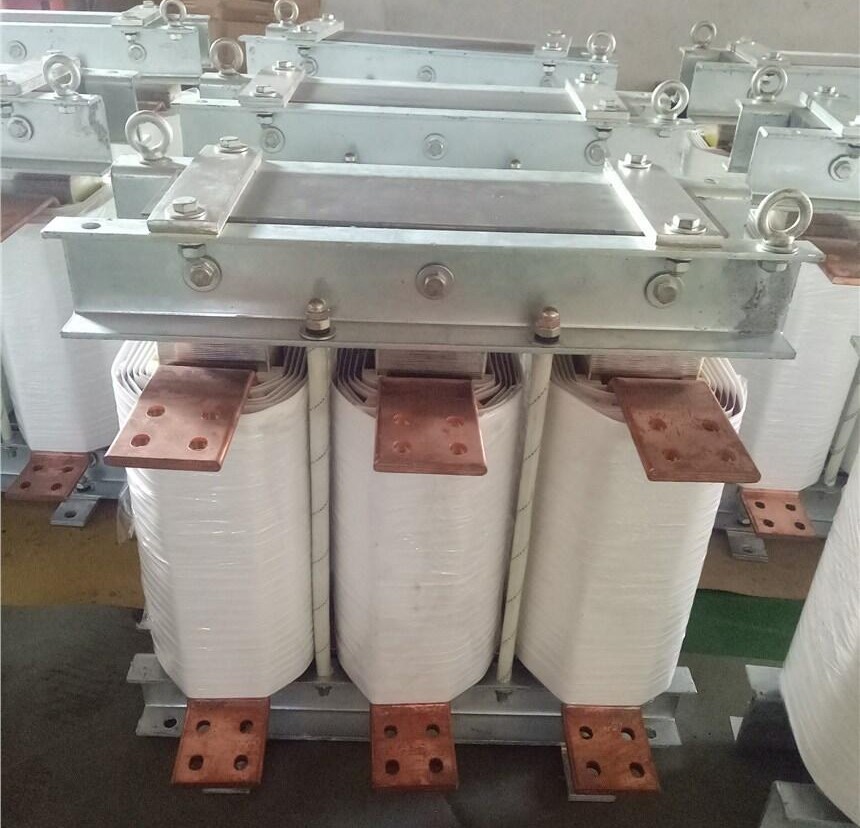
Copper/Aluminum Line Reactors for VFD – Essential Electrical Control Panel Component
Brand name: HANI
Packing Details : Wooden box with fumigation or Wooden Fram or Steel Frame
Delivery Details: 30~60days or Based on the quantity
Shipping: Sea freight、Land freight、Air freight
HANI specializes in industrial electrical automation, delivering integrated drive and control solutions to safeguard your production.
Product Details
Copper/Aluminum Line Reactors for VFD – Essential Electrical Control Panel Component
Line reactors sit at the intersection of power quality, equipment longevity and control panel reliability. In an era where industrial automation products are tasked with ever more demanding roles, the humble line reactor is anything but optional. Whether your facility relies on heavy-duty AC Drives & VFDs to coordinate production lines or you integrate complex Electrical Control Panel assemblies for global customers, the conductor material inside those reactors—copper or aluminum—directly shapes thermal performance, energy efficiency and installation practicality. At HANI, we see component selection as an engineering decision, not a commodity choice.
Key insight: A line reactor is one of the most cost-effective industrial automation products for extending the service life of variable frequency drives. When designed and specified correctly, it suppresses harmonic currents, reduces nuisance tripping and protects the semiconductor front-end of an AC Drives & VFDs system. The material choice—copper or aluminum winding—influences heat dissipation, footprint and long-term connection integrity inside every Electrical Control Panel.
1. What exactly is a line reactor and why does it matter for VFDs?
A line reactor is a three-phase inductor placed on the input (line side) or output (load side) of an AC drive. Physically, it is a core-and-coil assembly—laminated steel core with copper or aluminum windings—encased in a housing ready for mounting inside an Electrical Control Panel. Electrically, it introduces inductive reactance (XL = 2πfL) into the circuit, limiting the rate of current rise (di/dt) and offering impedance to higher frequency components. This simple electromagnetic principle delivers profound operational benefits for AC Drives & VFDs.
From a industrial automation products perspective, the line reactor is both a protective device and a power quality tool. It helps absorb voltage spikes coming from the utility or generated by drive commutation, and it reduces the total harmonic current distortion drawn by the rectifier stage. Without sufficient impedance, a VFD’s DC bus capacitors are stressed by sharp current pulses, leading to premature aging. A correctly sized line reactor smooths these pulses, directly contributing to the reliability of the entire automation installation.
2. The electromagnetic fundamentals with practical weight
The science behind a line reactor rests on Faraday’s law and the behaviour of magnetic materials under AC excitation. When current flows through the winding, a magnetic flux is established in the core. As alternating current changes direction, the collapsing and building flux induces a counter-electromotive force (CEMF) that opposes rapid changes. This is the inductive reactance that gives the reactor its current-limiting characteristic. The impedance Z is governed mainly by the inductance L, which itself depends on core geometry, number of turns, and magnetic permeability.
Harmonic mitigation arises because reactance increases linearly with frequency: XL = 2πfL. For 5th harmonic (250 Hz in 50 Hz systems) or 7th harmonic (350 Hz), the reactor presents significantly higher impedance than at the fundamental 50/60 Hz. This selective impedance naturally attenuates harmonic currents without the complexity of active filters. As part of a robust Electrical Control Panel design, this passive filtering approach remains a preferred strategy among industrial automation products due to its simplicity and MTBF figures often exceeding 15 years.
3. Copper vs. aluminum windings – a technical comparison that drives panel design
One of the most debated topics among panel builders and original equipment manufacturers is whether to specify copper or aluminum winding conductors in line reactors. Both options appear in quality industrial automation products, but their physical properties lead to distinct engineering trade-offs. The table below summarises the measurable differences based on IACS (International Annealed Copper Standard) conductivity, density and thermal behaviour.
| Parameter | Copper (Cu) Winding | Aluminum (Al) Winding |
|---|---|---|
| Electrical conductivity | 100 % IACS (≈ 5.96×10⁷ S/m) | ≈ 61 % IACS (3.5×10⁷ S/m) |
| Density | 8.96 g/cm³ | 2.70 g/cm³ |
| Thermal conductivity | ~ 400 W/(m·K) | ~ 235 W/(m·K) |
| Cross-section for equivalent resistance | Reference (1x) | Approximately 1.56x larger |
| Weight for equivalent conductivity | Reference (1x) | ~ 0.48x (about half the weight) |
| Coefficient of thermal expansion | ≈ 16.5 ×10⁻⁶ /K | ≈ 23.1 ×10⁻⁶ /K |
| Typical connection technology | Standard tin-plated copper lugs/pads | Requires bi-metallic lugs or AL/CU-rated terminals |
The table reveals why both materials thrive in different segments. Copper-based reactors are traditionally specified where panel real estate is tight and thermal dissipation is maximized through conduction. Aluminum windings, often encapsulated in high-temperature resin, are popular in larger reactors where weight reduction eases mounting structure requirements within the Electrical Control Panel. Many of today’s industrial automation products provide both options, and at HANI we work with customers to cross-reference the specific electrical and mechanical constraints of their control panel.
From a physics standpoint, the skin effect at harmonics also plays a subtle role. At 350 Hz, the skin depth in copper is about 3.5 mm, meaning solid conductors beyond this diameter do not fully utilize their core. Both copper and aluminum designs can be optimized with transposed strands or foil windings. However, because aluminum inherently requires larger cross-sections, the skin effect can partially offset the conductivity disadvantage if the design uses thin foil windings, making aluminum reactors surprisingly competitive for harmonic-heavy environments.
4. Why a line reactor belongs in every VFD electrical control panel
Integrating a line reactor inside the Electrical Control Panel is not simply about meeting a specification—it is about guaranteeing the performance of entire automated lines. Here are six data-backed reasons that elevate line reactors among critical industrial automation products:
- 1. DC Bus capacitor protection. By adding 3 % or 5 % impedance, peak charging current into the DC link capacitors can be reduced by 30–50 %. This directly extends capacitor life, which is statistically the number one failure mode in AC Drives & VFDs.
- 2. Harmonic current mitigation. A 3 % reactor typically reduces total harmonic current distortion (THDi) from roughly 80–120 % down to 35–45 %. When combined with a 5 % reactor or DC link choke, compliance with IEEE 519 recommendations becomes achievable without multi-pulse transformers.
- 3. Transient and surge suppression. Reactors attenuate voltage spikes that can arrive from utility-side switching or lightning-induced transients, protecting the drive’s input rectifier and reducing nuisance over-voltage trips.
- 4. dv/dt reduction on motor cables. Output reactors reduce the rate of voltage rise at the motor terminals, mitigating insulation stress and bearing currents. This is especially important when motor cable lengths exceed 15–20 meters.
- 5. Short-circuit current limiting. In the event of a downstream fault, line reactors slow the current rise, giving protection devices time to coordinate and reducing let-through energy.
- 6. Panel thermal compliance. Well-designed copper or aluminum reactors with adequate ventilation contribute to predictable airflow inside the Electrical Control Panel, supporting thermal management and avoiding hot spots that degrade adjacent industrial automation products.
5. Understanding % impedance and how it influences VFD selection
Reactors are typically rated by percent impedance at the fundamental frequency. Common values are 1.5 %, 3 % and 5 %. The percentage expresses the voltage drop across the reactor as a fraction of the drive’s rated input voltage when carrying full load current. A 3 % 400 V line reactor drops about 12 V at rated current. While this reduces slightly the voltage available at the drive terminals, modern AC Drives & VFDs contain voltage compensation routines, making the drop transparent to motor performance up to certain limits.
Higher impedance reactors (5 %) provide stronger harmonic attenuation and better protection, but they are physically larger, can generate more heat, and might reduce the maximum available motor voltage under heavy load. Most general-purpose industrial automation products recommend 3 % reactors as an optimal balance for line-side protection. For applications with a soft grid (high available fault current relative to drive kVA), 5 % can be justified. The table below gives approximate harmonic current distortion achieved for a typical 6-pulse diode rectifier VFD without internal DC choke.
| Reactor impedance (%Z) | Approx. Line THDi (%) | Typical use case |
|---|---|---|
| None (source only) | 85 – 130 % | Small standalone VFDs, very stiff grid acceptable |
| 1.5 % | 50 – 70 % | Light-duty, minimal panel space |
| 3 % | 35 – 45 % | Most industrial automation products & standard control panels |
| 5 % | 25 – 35 % | Sensitive environments, IEEE 519 compliance path |
It is important to note that actual THDi varies with source impedance, drive topology and loading. Nonetheless, the trend is clear: even a modest 3 % reactor can cut harmonic emission by more than half. In the context of industrial automation products, this directly translates into fewer interference problems with PLCs, sensors and communication networks sharing the same Electrical Control Panel ecosystem.
6. Thermal design: How copper and aluminum affect panel cooling strategy
Heat generation in a reactor is predominantly I²R loss in the winding plus core losses (hysteresis and eddy currents). For a given inductance and current rating, the I²R component depends on the conductor resistivity and cross-section. Because an aluminum winding needs about 56 % more cross-sectional area to match the resistance of a copper winding, the overall copper volume (and thus weight) trade-off emerges. However, the larger aluminum winding has more surface area, helping convection-based heat dissipation. This is why some aluminum reactors—despite higher absolute resistivity—can operate with similar temperature rises when designed appropriately.
In a sealed Electrical Control Panel with limited ventilation, the thermal time constant and heat rejection rate matter. Copper’s higher thermal conductivity helps pull heat from the core to the surface faster, but it also means heat can reach terminals more efficiently, requiring careful lug design. Aluminum’s lower density and often larger physical form allow heat to be dissipated across a larger envelope, but connection points must be meticulously prepared to prevent galvanic corrosion when mated with copper busbars. These are not trivial details—they influence long-term reliability of AC Drives & VFDs installations and panel uptime.
7. Manufacturing excellence and material verification
High-quality reactors—whether copper or aluminum—rely on precision winding, vacuum pressure impregnation (VPI) or trickle resin coating to eliminate voids and enhance mechanical rigidity. This prevents winding movement under inrush forces, which can reach several times nominal current. A robust varnish also seals against moisture ingress, a critical factor in industrial automation products deployed in tropical or unheated environments. The core lamination grade (typically M6 or better silicon steel) directly affects iron losses; inferior grades may save upfront cost but generate 15–20 % more heat for the same design, working against the overall Electrical Control Panel thermal budget.
At HANI, we specify reactors that go through routine testing including inductance verification at rated current, hipot (dielectric) testing between windings and core, and temperature rise testing under specified load profiles. This verification loop ensures that the reactor’s impedance curve holds within tolerance even as the core approaches saturation—because an undersized iron core can saturate on voltage peaks, suddenly losing inductance and sending a surge of harmonic current through the AC Drives & VFDs. That’s the kind of hidden failure mode that separates commodity components from genuine industrial automation products.
8. Proper selection and sizing for your electrical control panel
Selecting the correct line reactor involves more than matching current ratings. Engineers must consider:
- Voltage class: 208–240 V, 400–480 V, 575–690 V. Reactors are designed for specific insulation systems.
- Fundamental frequency: 50 or 60 Hz. Using a 50 Hz reactor on 60 Hz increases impedance proportionally; this is sometimes deliberately done to achieve higher harmonic rejection.
- Current rating: Continuous current should not exceed the rated thermal current. Some derating factors apply to high ambient temperature (>40 °C) or altitude above 1000 m.
- Inductance tolerance: Typically ±5 % to ±10 %. For parallel drive applications, tighter tolerance is preferable.
- Short-circuit withstand: A reactor must survive fault conditions. Look for tested ratings according to IEC or UL standards.
- Enclosure type and cooling: Open type (inside ventilated Electrical Control Panel) is the most common. NEMA 1 or encapsulated versions suit standalone mounting.
Panel space planning is another area where copper and aluminum diverge. A copper-wound reactor may be physically smaller but notably heavier, requiring reinforced mounting plates. An aluminum reactor, lighter but bulkier, needs more wiring space. For high-density industrial automation products panels where every cubic centimeter counts, copper often wins; for standalone wall-mounted cabinets with less weight-bearing capacity, aluminum becomes the pragmatic choice.
9. Installation best practices inside the electrical control panel
A line reactor, though robust, must be placed carefully to maximize its benefit and avoid unintended heating. Recommendations include:
- Mount the reactor away from sensitive electronics; its magnetic field can couple into adjacent circuit boards. A minimum distance of 150–200 mm from PLC or communication modules is typical.
- Keep the reactor at the bottom of the Electrical Control Panel if possible, as it generates heat that should rise away from logic components. Ensure unimpeded airflow.
- Use recommended cable sizes for termination. For aluminum winding reactors with copper bus, use approved bi-metallic connectors to prevent galvanic corrosion. Apply antioxidant compound if recommended by the manufacturer.
- Check torque values after 48 hours of initial operation; thermal cycling can loosen connections, especially in AC Drives & VFDs that see frequent start/stop cycles.
- A line reactor and an input filter or harmonic filter serve different purposes; do not substitute one for another without understanding the impedance impact.
These installation details further underline that line reactors are not standalone add-ons but integral industrial automation products whose performance depends on correct integration into the larger Electrical Control Panel context.
10. The HANI perspective: matching reactor material to application realities
With extensive experience supplying industrial automation products worldwide, HANI recognizes that the copper-versus-aluminum decision is not about a fixed hierarchy. Industries with high vibration (e.g., mining conveyors, crushers) may prefer copper’s mechanical robustness and higher fatigue resistance at terminations. Water treatment plants in coastal areas often favour aluminum reactors with specialized epoxy encapsulation to resist corrosive atmospheres, combined with bi-metallic terminations. In both scenarios, the underlying mission is identical: protect the AC Drives & VFDs, ensure clean power, and maintain uptime.
HANI’s engineering support helps clients evaluate total lifecycle cost: initial purchase price, installation labour, thermal management adjustments, and a de-rated service life projection. Often, a well-designed 3 % aluminum open-type reactor becomes the most economical choice over a 10-year horizon for a standard 480 V 100 hp drive, assuming proper termination practices. In contrast, a compact machine builder integrating twenty small VFDs into one densely packed Electrical Control Panel might never consider aluminum due to space constraints.
Frequently Asked Questions
Q: Is a line reactor the same as a load reactor or a choke?
A line reactor typically refers to an input (line-side) inductor. A load reactor is placed on the output (motor side) of the VFD. Both are inductors; the terminology denotes location. A DC choke sits in the DC link. While design principles overlap, a line reactor is specifically engineered to protect the AC Drives & VFDs from grid-side disturbances and to limit harmonic current propagation. All are essential industrial automation products in comprehensive panel design.
Q: Can I use an aluminum-wound reactor as a direct replacement for a copper one?
Yes, provided that the electrical ratings (inductance, current, impedance) match and that the physical dimensions and termination compatibility are respected. Pay extra attention to the connection requirements: an aluminum reactor usually needs lugs rated for AL/CU and may require slightly different torque settings. Always confirm with the manufacturer or your trusted source of industrial automation products.
Q: Do line reactors eliminate the need for harmonic filters?
Not completely. A line reactor significantly reduces harmonic currents but cannot achieve the very low THDi levels possible with active front-end drives or multi-pulse active filters. For many applications, however, a 3 % or 5 % reactor combined with a DC choke brings the installation into compliance with IEEE 519 without the expense of a filter. In a well-designed Electrical Control Panel, the reactor works as the first line of defense—a silent, constant-duty component among industrial automation products.
Q: How do I choose between a 3 % and 5 % impedance reactor?
Start with the drive manufacturer’s recommendation. If you need maximum harmonic mitigation and voltage drop is acceptable, 5 % is the conservative choice. For critical processes, a 3 % reactor plus a DC link choke may offer comparable harmonic performance with less voltage reduction. Evaluate the supply transformer impedance as well; stiff grids generally benefit from higher reactor impedance.
Q: Are copper reactors always better for heat dissipation?
Copper has higher thermal conductivity, but total heat dissipation depends on surface area, airflow, and core design. A well-engineered aluminum reactor with a large surface area can run at a similar or even lower temperature rise than a compact copper unit. The panel builder’s layout and cooling strategy often determine which material yields superior thermal performance in an Electrical Control Panel full of AC Drives & VFDs and other industrial automation products.
11. The broader context: line reactors as pillars of system reliability
Returning to the physics, the iron-core reactor stores energy in its magnetic field during each half-cycle and returns most of it to the circuit. This reactive power exchange, measured in kVAR, does not consume real power except for losses—typically 0.5 % to 2 % of the drive rating. When we speak of industrial automation products that contribute to energy efficiency, reactors play a subtle role: by smoothing current and reducing harmonic distortion, they improve true power factor as seen by the transformer, decrease I²R losses in supply cables, and avoid the need to oversize transformers and generators. A 3 % line reactor might pay back its cost through avoided infrastructure upgrades alone when multiple VFDs are clustered in a factory.
Reactor winding material, copper or aluminum, becomes part of this engineering narrative. Advanced manufacturers now use hybrid designs: copper primaries for low current, high frequency sections, with aluminum secondary windings where size is less constrained. The evolution of AC Drives & VFDs towards higher power density and integrated intelligence means the traditional line reactor is also being reimagined—thinner laminations, improved core steels, and vacuum encapsulation techniques that reduce partial discharge and acoustic noise.
12. Final engineering considerations and a call to action
Before specifying a copper or aluminum line reactor for your next Electrical Control Panel, map the complete electrical and thermal context: steady-state current, overload duty cycle, ambient temperature extremes, altitude, harmonic spectrum, and physical constraints. Use the tables in this article as a starting framework, and always cross-check with manufacturer data sheets that show temperature rise versus load curves. Remember that a reactor is a life-of-the-installation asset—its MTBF, when installed correctly, reaches into the millions of hours, making it one of the most reliable industrial automation products inside any panel.
At HANI, we bring this engineering depth to every inquiry. Whether you need a standard 3 % 480 V reactor or a custom impedance design for a special AC Drives & VFDs retrofit, the goal is always clear: a cleanly engineered, long-lasting power interface that protects your capital equipment. The right reactor—copper or aluminum—transforms a basic VFD installation into a resilient automation platform ready for years of demanding operation.
Explore line reactor solutions for your VFD panels → Talk with a HANI specialist about matching reactor material, impedance and footprint to your industrial automation products requirements. Achieve reliable harmonic control and equipment protection from the heart of your Electrical Control Panel.
HANI is one of China’s leading professional industrial electrical automation manufacturers, providing complete drive and control solutions to customers worldwide. HANI focuses on designing and manufacturing integrated automation systems that meet the industry’s highest standards of precision, efficiency, and durability. Our engineering expertise lies in providing turnkey electrical automation projects to optimize the performance of modern industrial manufacturing plants.