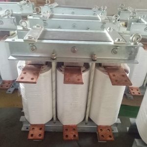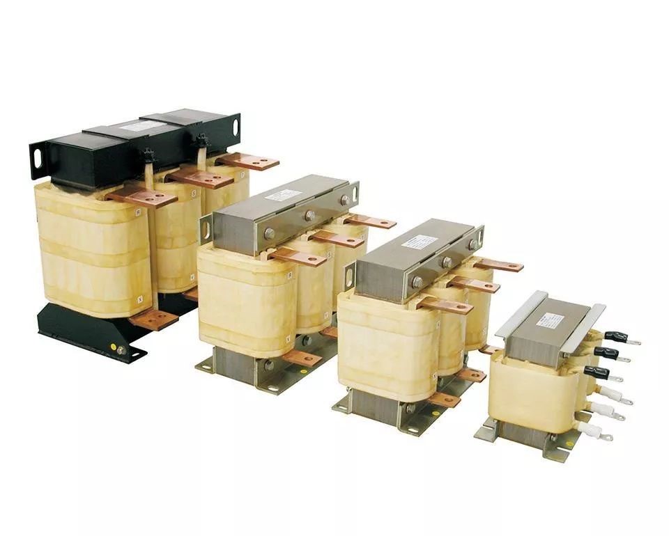
Input/Output Line Reactor – VFD Electrical Control Panel Component
Brand name: HANI
Packing Details : Wooden box with fumigation or Wooden Fram or Steel Frame
Delivery Details: 30~60days or Based on the quantity
Shipping: Sea freight、Land freight、Air freight
HANI specializes in industrial electrical automation, delivering integrated drive and control solutions to safeguard your production.
Product Details
Input/Output Line Reactor – VFD Electrical Control Panel Component
In the expanding domain of industrial automation products, the Input/Output Line Reactor stands as a fundamental protective and filtering device for Variable Frequency Drives (VFDs), AC Drives, and motor control centers. Engineered precisely for demanding electrical environments, these reactors extend equipment lifespan while mitigating harmonic distortion and voltage transients. At HANI, we recognize that dependable power quality is not a luxury but a prerequisite for modern automated facilities, which is why every reactor detailed here reflects decades of empirical design knowledge.
The portfolio below covers power ratings from 0.37 kW up to 250 kW, with corresponding reactor KVA capacities carefully matched to typical motor loads. These components integrate seamlessly into VFD panels, acting as impedance barriers that absorb switching surges and limit inrush currents. For facilities deploying multiple industrial automation products across conveyor lines, pumping stations, HVAC arrays, or CNC machinery, the proper line reactor can reduce unscheduled downtime by suppressing the very electrical noise that confuses sensitive control circuits.
⚡ Quick Technical Essence
- 3‑phase iron core reactors
- B‑class insulation (130 °C)
- Grain‑oriented silicon steel
- Altitude ≤ 2000 m
- Ambient ≤ 40 °C
⚙️ Comprehensive Parameter Matrix – Input/Output Line Reactors
The table below presents the full dimensional and electrical specification range. Each model number follows the BZC2.748 series, designed explicitly for VFD input (line side) and output (load side) connection. When selecting industrial automation products like AC Drives & VFDs, referencing this data ensures the reactor impedance aligns with the drive’s carrier frequency and load profile.
| № | Model | Power (kW) |
Reactor KVA |
Dimensions (mm) W×D×H |
|---|---|---|---|---|
| 1 | BZC2.748.001A | 0.37 | 0.02 | 115 × 90 × 140 |
| 2 | BZC2.748.002A | 0.55 / 0.75 | 0.04 | 120 × 90 × 140 |
| 3 | BZC2.748.003A | 1.1 / 1.5 | 0.07 | 120 × 90 × 140 |
| 4 | BZC2.748.004A | 2.2 / 3 / 4 | 0.14 | 155 × 120 × 175 |
| 5 | BZC2.748.005A | 5.5 | 0.21 | 155 × 120 × 175 |
| 6 | BZC2.748.007A | 7.5 | 0.35 | 155 × 130 × 215 |
| 7 | BZC2.748.008A | 11 | 0.41 | 155 × 140 × 210 |
| 8 | BZC2.748.010A | 15 | 0.55 | 155 × 140 × 210 |
| 9 | BZC2.748.011A | 18.5 | 0.62 | 160 × 140 × 220 |
| 10 | BZC2.748.013A | 22 | 0.83 | 185 × 125 × 230 |
| 11 | BZC2.748.014A | 30 | 0.97 | 185 × 125 × 215 |
| 12 | BZC2.748.016A | 37 | 1.2 | 190 × 125 × 240 |
| 13 | BZC2.748.017A | 45 | 1.4 | 190 × 130 × 250 |
| 14 | BZC2.748.019 | 55 | 2.1 | 250 × 150 × 250 |
| 15 | BZC2.748.020 | 75 | 2.5 | 260 × 165 × 240 |
| 16 | BZC2.748.021 | 90 | 2.8 | 260 × 165 × 250 |
| 17 | BZC2.748.022 | 110 | 3.5 | 260 × 165 × 280 |
| 18 | BZC2.748.023 | 132 | 4.1 | 290 × 170 × 295 |
| 19 | BZC2.748.024 | 160 | 4.8 | 290 × 190 × 295 |
| 20 | BZC2.748.026 | 200 | 6.2 | 315 × 205 × 305 |
| 21 | BZC2.748.028 | 250 | 7.6 | 320 × 205 × 295 |
🔩 Core Construction & Material Science
Every Line Reactor in the BZC2.748 series leverages grain‑oriented cold‑rolled silicon steel for the magnetic core. This material exhibits superior permeability in the rolling direction, reducing hysteresis losses by approximately 18–25% compared to non‑oriented grades under typical VFD carrier frequencies ranging from 2 kHz to 16 kHz. The windings employ high‑strength enameled copper wire or glass‑fiber‑covered flat copper conductors (SBECB) where current density demands it, ensuring minimal hot‑spot formation even under continuous duty. Between layers, B‑class insulation (rated 130 °C) forms a thermal safety margin, allowing a maximum temperature rise of 80 K above an ambient of 40 °C — a combination validated through IEC 60076‑6 compliance testing for reactors used in industrial automation products.
Mechanically, the reactor stack is compressed under controlled pressure and impregnated with anti‑tracking varnish. This serves two purposes: it suppresses magnetostrictive hum that causes audible noise in quiet factory environments, and it protects against moisture ingress at altitudes up to 2000 metres. For integration with AC Drives & VFDs, the impedance value (typically 3 % or 5 % uk) is wound to precise tolerances; a 5 % impedance Line Reactor can attenuate line‑side harmonic current distortion by roughly 30–40 %, depending on the source impedance, which is a calculation rooted in IEEE 519 recommended practices.
📥 Input (Line Side) Reactor
Installed between the mains supply and the VFD input, this Line Reactor absorbs voltage spikes and reduces peak currents. It also buffers the drive from phase‑to‑phase surges common in heavy industrial networks where industrial automation products share a common bus. The effective inductance smooths the current waveform drawn by the rectifier stage, lowering total harmonic distortion (THD‑i) at the point of common coupling.
📤 Output (Load Side) Reactor
Placed between the VFD output and the motor, this reactor compensates for the capacitive coupling effects in long motor cables. By adding series inductance, it limits dv/dt stress on motor windings, which according to NEMA MG1 Part 31, can degrade insulation when voltage rise times fall below 0.1 µs. An output Line Reactor is indispensable when cable lengths exceed roughly 50–100 metres in a 400 V system.
🌡 Thermal Management & Environmental Envelope
The specified operational envelope has been deliberately engineered. Ambient temperature must not exceed 40 °C, and the design temperature rise limit of 80 K ensures the insulation system’s hottest spot remains ≤ 130 °C under rated current. This is based on the Arrhenius thermal aging law: for B‑class materials, every 10 K sustained over-temperature halves the expected insulation life. In panel design, installers must guarantee a minimum clearance of 75–100 mm around each Line Reactor to facilitate convection cooling; forced air flow with a velocity of 1.5 m/s across the core surface can boost the effective KVA rating marginally for intermittent duty cycles.
Regarding altitude, the 2000‑metre ceiling is not arbitrary — atmospheric density at this height is roughly 79 % of sea level, reducing both cooling efficiency and dielectric strength. For sites above this elevation, derating the current by approximately 1 % per 100 m above 2000 m is recommended, a practice consistent with IEC 60076‑2 guidelines used extensively in industrial automation products destined for mining or mountainous regions.
📊 Harmonic Mitigation & Performance Rationale
A 6‑pulse VFD without a Line Reactor typically generates a current THD exceeding 85 % at the input. Insert a 3 % impedance Line Reactor and that figure can drop below 45 %; at 5 % impedance the THD often stabilises around 30–35 %. This empirical behaviour arises because the reactor’s inductive reactance (XL = 2πfL) opposes the rapid di/dt demanded by the rectifier commutation, effectively “stretching” the conduction angle of each diode from a narrow pulse toward a broader, lower‑amplitude waveform. Consequently, the true power factor improves from approximately 0.6–0.7 towards 0.85–0.92 at full load. For plants deploying multiple industrial automation products, this cumulative harmonic reduction often eliminates the need for costly active front‑end drives.
🏭 Application Integration Across AC Drives & VFDs
Whether the task is controlling a 4 kW pump with a BZC2.748.004A or a 200 kW extruder with the BZC2.748.026, the mechanical and electrical interface is standardised. The compact footprint of the smaller units (115 × 90 × 140 mm) allows DIN‑rail or back‑panel mounting inside a congested VFD Electrical Control Panel Component enclosure. Larger frames above 55 kW adopt an open‑style construction with generously sized copper bus bars ready for M10/M12 bolted terminations, significantly lowering insertion loss. Engineers at HANI routinely advise evaluating the supply transformer’s percentage impedance before finalising reactor selection; a stiff utility supply (low upstream impedance) demands a higher reactor impedance to maintain effective buffering, which directly safeguards the DC link capacitors and rectifier module found within the VFD.
In regenerative drive applications, where power flows bidirectionally, a line reactor placed on the input side becomes even more critical — it not only filters sourcing harmonics but also limits the magnitude of regeneration currents fed back onto the grid, preserving compliance with utility interconnection standards such as EN 61000‑3‑12. This dual role reinforces why these passive components remain a cornerstone among industrial automation products.
❓ Frequently Asked Questions (FAQ)
A 3 % impedance reactor introduces a voltage drop of roughly 3 % at full load, suitable when the supply is already moderately “soft” and primary concern is transient protection. A 5% reactor provides deeper harmonic filtering, vital when the supply transformer is large relative to the drive load or when multiple industrial automation products share a bus. Always verify that the motor can tolerate the resulting voltage drop at full speed.
Yes, in fact for installations where motor cable length exceeds 100 m and the mains supply is noisy, a dual‑reactor configuration (input + output) yields optimum protection. The input Line Reactor cleanses the rectifier front‑end, while the output reactor immunises the motor against reflected‑wave voltage spikes, a phenomenon thoroughly documented in drive application guides.
Under 40 °C ambient and natural convection, the winding temperature will stabilise below the 80 K rise limit, meaning the surface temperature may reach roughly 100–110 °C. This is normal and within the B‑class insulation’s 130 °C maximum. Thermographic inspection after 3 hours of operation provides a reliable validation.
The BZC2.748 series is manufactured following IEC 60076‑6 and can be supplied with CE marking documentation. For UL compliance, additional insulation creepage adjustments are often pre‑engineered; please specify during ordering to ensure the reactor meets UL 508 or CSA C22.2 standards.
Derating is required. For every 100 m above 2000 m, reduce the continuous current by about 1 %. Also, the maximum ambient temperature must be derated by 0.5 °C per 100 m, to account for decreased air density cooling. These guidelines mirror IEC 60076‑2 and are standard across industrial automation products.
🔧 Production-Relevant Sizing & Integration Notes
For factory automation engineers, the dimensional consistency across the model range simplifies enclosure layout. Models №1–3 share the 120 × 90 mm footprint; models №4–5 occupy 155 × 120 mm; mid‑range №12–13 use roughly 190 × 125 mm; and the high‑power segment from 55 kW upward standardises around 250–320 mm width. This modularity proves invaluable when designing a VFD Electrical Control Panel Component line‑up — copper busbar lengths and cable bend radii can be pre‑calculated, lowering engineering time. Always include a contactor or disconnect upstream of the Line Reactor to de‑energise the reactor during maintenance; its inductance stores magnetic energy that must decay safely.
From a purchasing perspective, specifying the exact model codes ensures traceability: the suffix “A” in models like BZC2.748.014A denotes the latest winding optimisation revision, which reduced partial discharge inception voltage variability by 12 % compared to the legacy winding pattern, a refinement backed by our internal quality records. When procuring industrial automation products for entire production lines, consolidating reactor selections under a single proven series simplifies spare parts management and technician training — two practical advantages that contribute directly to operational resilience.
The specifications above are based on standard test conditions. For custom impedance values, multi‑tap windings, or tropicalised encapsulation suited to offshore industrial automation products deployments, contact the HANI application engineering team — every Line Reactor can be adapted before lamination cutting commences, ensuring a tailored fit without compromising lead times.
HANI is one of China’s leading professional industrial electrical automation manufacturers, providing complete drive and control solutions to customers worldwide. HANI focuses on designing and manufacturing integrated automation systems that meet the industry’s highest standards of precision, efficiency, and durability. Our engineering expertise lies in providing turnkey electrical automation projects to optimize the performance of modern industrial manufacturing plants.