Heatsink for Thyristor – Thermal Management in Electrical Control Panels
Brand name: HANI
Packing Details : Wooden box with fumigation or Wooden Fram or Steel Frame
Delivery Details: 30~60days or Based on the quantity
Shipping: Sea freight、Land freight、Air freight
HANI specializes in industrial electrical automation, delivering integrated drive and control solutions to safeguard your production.
Product Details
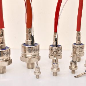
In the domain of power electronics, the thyristor stands as one of the most rugged and widely deployed semiconductor devices—capable of switching kiloamperes of current and withstanding kilovolts of blocking voltage. Yet, for all its electrical robustness, the thyristor’s Achilles’ heel is heat. Without rigorous thermal management, even the most conservatively rated SCR or triac will drift out of specification, age prematurely, or fail catastrophically. The component that bridges this gap between electrical capability and thermal reality is the heatsink for thyristor.
This article provides a comprehensive examination of heatsink for thyristor selection, design, and integration within electrical control panels. Written with the practicing engineer and panel builder in mind, it draws on established principles of thermal management in power electronics, referencing standards such as IEC 60747-6 and published thermal conductivity data. Where practical, we reference specific industrial automation products and real-world mounting configurations, including solutions offered by HANI for panel-level thermal integration.
1. The Thermal Imperative: Why Thyristors Demand Dedicated Cooling
A thyristor is a bipolar device. In the on-state, it sustains a forward voltage drop—typically between 1.2V and 2.5V for a standard phase-control SCR, depending on junction temperature and current density. When multiplied by the load current, this forward drop yields conduction losses that can easily reach hundreds of watts in a single module. During commutation and turn-on, additional switching losses manifest, though these are generally smaller than conduction losses at line frequencies.
Semiconductor physics imposes hard thermal ceilings. Silicon thyristors are typically rated for a maximum junction temperature (Tjmax) of 125°C, with some industrial modules extending to 150°C. Exceeding this threshold—even transiently—triggers thermal runaway: increased intrinsic carrier concentration drives up leakage current, which raises temperature further, which increases leakage, until the device is destroyed. This positive-feedback mechanism is unforgiving and demands that every heatsink for thyristor be sized with a safe thermal margin.
The thermal design of power semiconductor systems is governed by the standard IEC 60747-6, which specifies terminology, rating methods, and test procedures for thyristors including partial thermal resistance definitions junction-to-case[reference:0]. These standards underpin the datasheet parameters that engineers use to calculate the required heatsink for thyristor thermal resistance. Panel builders working with industrial automation products must interpret these parameters correctly to ensure long-term reliability in field-deployed equipment.
2. The Thermal Resistance Network: Modeling Heat Flow
The most powerful conceptual tool in thermal management is the electrical circuit analogy. Heat flowing from the semiconductor junction to the ambient air is analogous to current flowing through a series of resistors. Power dissipation (PD in watts) is the “current”; temperature difference (ΔT in °C) is the “voltage”; and each interface along the path has a thermal resistance (Rth in °C/W).
The fundamental heat transfer equation for power dissipation is:
where ΔT is the temperature difference driving heat flow, and ΣRθ is the sum of all thermal resistances in the path[reference:1]. For a thyristor mounted on a heatsink for thyristor, the full network is:
| Thermal Resistance | Symbol | Description | Typical Range (TO-240 / Capsule) |
|---|---|---|---|
| Junction-to-Case | Rth(j-c) | Internal thermal impedance of the semiconductor package; fixed by design | 0.03 – 0.15 °C/W |
| Case-to-Sink (Interface) | Rth(c-s) | Resistance across TIM, mounting surface flatness and clamping pressure | 0.01 – 0.10 °C/W (with TIM) |
| Sink-to-Ambient | Rth(s-a) | The heatsink’s own thermal resistance to the surrounding air | 0.12 – 4.0 °C/W (varies by size & airflow) |
The calculation procedure for selecting a heatsink for thyristor follows a logical four-step process: determine power dissipation, define the maximum allowable junction temperature, calculate the maximum allowable total thermal resistance, and then subtract the known junction-to-case and case-to-sink resistances to arrive at the required heatsink for thyristor sink-to-ambient resistance[reference:2]. For example, a thyristor dissipating 200W with Tjmax = 125°C, operating at Tamb = 40°C, yields a total allowable Rth of (125 − 40) / 200 = 0.425°C/W. Subtracting Rth(j-c) of 0.05°C/W and Rth(c-s) of 0.03°C/W leaves a required heatsink thermal resistance of 0.345°C/W.
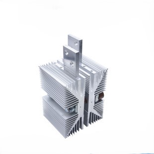
3. Heatsink Materials: Aluminum, Copper, and the Convection Bottleneck
The choice of heatsink material has a measurable but often misunderstood impact on overall thermal management performance. Pure aluminum (alloy 1050A) offers a thermal conductivity of approximately 229 W/m·K, while common extrusion alloys 6060 and 6063 deliver 166 and 201 W/m·K respectively, depending on temper[reference:3]. Copper, by comparison, provides roughly twice the conductivity—around 398–400 W/m·K—but at three times the density and four to six times the cost[reference:4].
The key insight, however, is that material conductivity is not always the limiting factor. Under natural convection conditions—which prevail in many passively cooled control panels—the bottleneck in heat transfer shifts from conduction within the metal to convection at the metal-air interface. In such scenarios, a copper heatsink for thyristor provides only a marginal improvement in °C/W over an equivalent aluminum design[reference:5]. Under forced convection with a fan, the advantage of copper becomes more pronounced because the convection coefficient at the air side increases, making the conduction path through the material relatively more significant[reference:6].
| Property | Aluminum (6063-T5) | Copper (C11000) |
|---|---|---|
| Thermal Conductivity (W/m·K) | ~200 | ~400 |
| Density (g/cm³) | ~2.7 | ~8.9 |
| Relative Cost | 1× | 4–6× |
| Extrudability | Excellent | Not extrudable (machined/skived) |
| Natural Convection Performance | Reference | Marginally better (convection-limited) |
| Typical Use Case | General-purpose industrial automation products | High-performance forced-air & liquid cooling |
For the vast majority of power electronics applications in industrial control panels, extruded aluminum represents the optimal balance of thermal performance, cost, weight, and manufacturability. The surface finish also matters: anodized (matte-black) surfaces can improve radiative heat transfer, which becomes a non-trivial contributor in still-air environments where natural convection dominates[reference:7].
4. The Thermal Interface: TIM Selection and Clamping
Between the thyristor baseplate and the heatsink for thyristor mounting surface lies a critical yet often overlooked element: the thermal interface material (TIM). Even when two metal surfaces appear smooth, microscopic surface roughness creates air gaps that severely impede heat flow. Without a TIM, the case-to-sink thermal resistance can be 0.5–2.0°C/W[reference:8].
TIMs fill these voids and reduce Rth(c-s) to between 0.01 and 0.10°C/W when properly applied[reference:9]. The range of available TIM technologies spans from simple silicone-based thermal greases (thermal conductivity ~1–5 W/m·K) to advanced metal-matrix composites and liquid-metal formulations that approach the conductivity of pure metals while maintaining interface compliance[reference:10]. Modern high-performance TIMs now target thermal conductivity values exceeding 5 W/m·K, with premium solutions reaching 10–25 W/m·K[reference:11].
| TIM Type | Thermal Conductivity (W/m·K) | Typical Rth(c-s) (°C/W) | Best For |
|---|---|---|---|
| Silicone Thermal Grease | 1 – 5 | 0.05 – 0.10 | General-purpose thyristor mounting |
| Phase-Change Material (PCM) | 3 – 8 | 0.03 – 0.07 | Cyclic thermal loads |
| Graphite Pad | 5 – 13 | 0.02 – 0.05 | High-reliability, no pump-out |
| Metal-Matrix / Liquid Metal | 20 – 80+ | 0.01 – 0.03 | Ultra-high-power modules |
Clamping force is equally critical. Thyristor modules—particularly those in capsule (hockey-puck) packages—require a specified mounting force, typically in the range of 10–25 kN, applied uniformly via a clamping system. Under-clamping elevates Rth(c-s) dramatically; over-clamping risks mechanical damage to the semiconductor die. Panel builders integrating industrial automation products should always follow the manufacturer’s torque specifications for screw-mounted modules, commonly 1.0–1.5 N·m for TO-240 packages[reference:12].
5. Cooling Methods: Natural Convection, Forced Air, and Advanced Solutions
The thermal management strategy for a heatsink for thyristor can be broadly categorized by the mechanism that removes heat from the fin surfaces to the environment. The choice depends on power density, ambient conditions, and reliability requirements.
5.1 Natural Convection (Passive Cooling)
Natural convection relies on buoyancy-driven airflow: as air near the fin surface heats up, its density decreases, creating an upward flow that is replaced by cooler ambient air. This method is silent, maintenance-free, and inherently reliable—no fans to fail. The trade-off is relatively high thermal resistance, typically in the range of 0.5–4.0°C/W depending on fin geometry and orientation[reference:13].
Natural convection is most suitable for thyristor systems dissipating less than approximately 50W, though it can be used at higher powers when large fin surface areas are available and the panel environment permits higher heatsink temperatures[reference:14]. Fin orientation matters greatly: vertical fin channels maximize chimney-effect airflow; horizontal mounting can reduce natural convection efficiency by 30–50%.
5.2 Forced Air Cooling
Adding a fan or blower to force air across the fin surfaces can reduce heatsink thermal resistance by a factor of 5 to 15 compared to natural convection[reference:15]. This enables significantly higher power densities in power electronics enclosures. A heatsink for thyristor with forced air cooling can achieve Rth(s-a) values as low as 0.12°C/W, allowing a single module to dissipate several hundred watts safely[reference:16].
The compromise is reliability and maintenance: fans have finite lifetimes (typically 40,000–70,000 hours at rated temperature), introduce acoustic noise, and may require filtered air intakes to prevent dust accumulation on fin surfaces—which itself increases thermal resistance over time.
5.3 Heat Pipes and Thermosiphons
For the most demanding thermal management challenges in high-power thyristor systems, two-phase cooling technologies offer transformative performance. Heat pipes exploit the latent heat of vaporization of a working fluid to transport heat with effective thermal conductivities thousands of times higher than solid copper[reference:17]. A thermosiphon operates on the same principle but uses gravity to return the condensed liquid, eliminating the need for a capillary wick structure and enabling passive, pump-free operation over longer transport distances[reference:18].
Loop thermosiphons have been demonstrated as effective solutions for cooling high-density power electronics where conventional air-cooled systems reach their limits[reference:19]. In a control panel context, a thermosiphon-based heatsink for thyristor can move heat from the semiconductor mounting surface to a remote fin stack positioned in a cooler air stream—dramatically improving system-level thermal management without the complexity of pumped liquid cooling. These represent some of the most innovative industrial automation products available for extreme thermal environments, and HANI has been working to bring such advanced cooling solutions within reach of system integrators.
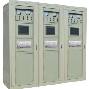
6. Panel Integration: Mounting Configurations and Airflow Design
The physical integration of a heatsink for thyristor into an electrical control panel involves more than bolting the device to a metal extrusion. The heatsink’s position, orientation, and proximity to other heat sources all influence system-level thermal management outcomes.
6.1 DIN Rail Mounting
DIN rail mounting has become a standard in industrial automation products for solid-state relay and thyristor assemblies. Heat sinks designed for 35mm DIN rail allow the entire assembly—relay or thyristor module plus heatsink—to be snapped into place without additional hardware. Products like the Carlo Gavazzi RHS series offer thermal resistances from 4.0°C/W down to 0.12°C/W in DIN-rail-mountable form factors, suitable for mounting one to three single-phase or one three-phase SSR[reference:20][reference:21]. Some designs, such as the Fischer Elektronik SK 89 series, incorporate guide grooves for cover plates or PCBs and can be snapped directly onto standard 35mm DIN rails[reference:22].
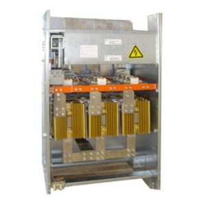
6.2 Panel and Through-Wall Mounting
Panel-mounted heat sinks attach directly to the enclosure backplane, offering robust mechanical support for heavier thyristor modules. Through-wall mounting goes a step further: the thyristor module is mounted on one side of the panel (often inside the sealed enclosure), while the heatsink for thyristor protrudes through a cutout to the exterior, exposing the fins to cooler ambient air outside the panel[reference:23]. This configuration can dramatically improve thermal management by decoupling the heatsink’s ambient environment from the panel’s internal temperature rise caused by other components.
| Mounting Type | Advantages | Limitations |
|---|---|---|
| DIN Rail (35mm) | Fast installation, modular, standard in panel building | Limited to smaller thermal masses; constrained cooling area |
| Panel Mount | Mechanically robust; good for large modules and multiple SSRs | Heatsink inside panel adds to internal heat load |
| Through-Wall | Fins exposed to external ambient; excellent thermal decoupling | Requires panel cutout; additional sealing for IP rating |
6.3 Airflow Management Inside the Panel
Even with properly sized heat sinks, poor airflow management can negate the benefits. Key design principles include: separating high-power thyristor assemblies from temperature-sensitive components such as PLCs and sensitive relays; ensuring adequate vertical clearance above and below fin channels for unimpeded natural convection; avoiding the placement of a heatsink for thyristor directly beneath another hot component where pre-heated air reduces the effective ΔT; and, in forced-air panels, orienting fans so that the coolest air reaches the thyristor heat sinks first.
7. Heatsink Selection: A Practical Step-by-Step Procedure
The following procedure distills the thermal design process into actionable steps for engineers specifying a heatsink for thyristor in industrial automation products.
Step 1 — Determine Power Dissipation (PD): For a thyristor, PD ≈ VT(avg) × IT(avg) for conduction losses, plus switching losses if operating at higher frequencies (consult the device datasheet for precise curves)[reference:24].
Step 2 — Establish Temperature Limits: Identify Tjmax from the datasheet (typically 125°C or 150°C for industrial thyristors). Determine the maximum expected ambient temperature (Tamb) inside the panel at the heatsink location—a value that must account for self-heating from other equipment.
Step 3 — Determine Rth(j-c) and Rth(c-s): Read Rth(j-c) from the thyristor datasheet and estimate Rth(c-s) based on the chosen TIM and mounting method.
Step 4 — Calculate Required Rth(s-a): Compute: Rth(s-a)_required = (Tjmax − Tamb) / PD − Rth(j-c) − Rth(c-s)[reference:25].
Step 5 — Apply Safety Margin: Derate by at least 20–25% to account for TIM degradation over time, dust accumulation, and manufacturing tolerances in heatsink thermal resistance figures. Derate further if the panel is subject to high altitudes (reduced air density impairs convection).
Step 6 — Select a Heatsink: Choose a heatsink for thyristor with Rth(s-a) ≤ calculated required value, verifying that the physical dimensions, mounting method, and fin orientation are compatible with the panel layout.
8. Common Failure Modes and Troubleshooting
Even a well-designed thermal management system can degrade over time or under unanticipated operating conditions. Understanding the most common failure modes helps prevent unplanned downtime in critical power electronics installations.
| Failure Mode | Root Cause(s) | Symptoms | Preventive Action |
|---|---|---|---|
| Thermal Runaway | Undersized heatsink; TIM degradation; fan failure | Rapidly escalating leakage current; device destruction | Adequate margin; thermal monitoring with trip circuit |
| TIM Pump-Out / Dry-Out | Thermal cycling; inadequate clamping pressure | Gradual increase in case temperature; intermittent trip | Use phase-change or graphite TIMs; re-torque periodically |
| Fin Fouling | Dust accumulation; oil mist; corrosive atmospheres | Progressive thermal derating; hot spots | Scheduled cleaning; filtered enclosures; conformal coating |
| Inadequate Airflow | Poor panel layout; blocked vents; failed fan | Elevated ambient inside panel; multiple device overheating | Thermal imaging survey; fan status monitoring |
9. Frequently Asked Questions
Q: How do I know if my thyristor needs a heatsink?
If the calculated junction temperature without a heatsink exceeds approximately 80% of Tjmax, a heatsink is essential[reference:26]. As a practical rule, most thyristors conducting more than a few amperes continuously require some form of dedicated thermal management.
Q: Can I mount multiple thyristors on a single heatsink?
Yes. Many industrial automation products support mounting one, two, or three thyristor or SSR modules on a common heatsink for thyristor. The total power dissipation must be summed, and the highest junction temperature among the devices must still remain within limits. Thermal coupling between devices must also be considered—the temperature rise contribution from adjacent modules adds to the local ambient for each device[reference:27].
Q: Does the surface finish of the heatsink matter?
Yes, though the effect depends on the cooling regime. In low-airflow or natural-convection scenarios, a matte-black anodized surface can improve radiative heat transfer by 10–20%. Under forced convection, the benefit is smaller because convection dominates the total heat transfer coefficient[reference:28].
Q: What is the difference between an SCR heatsink and an SSR heatsink?
Functionally, they are identical—both serve to dissipate heat from semiconductor junctions. The difference lies in mechanical compatibility: SSR heat sinks often include pre-drilled mounting patterns for specific relay form factors, while a heatsink for thyristor in a disc/capsule package uses a clamp assembly. Many modern designs are compatible with both thyristor modules and solid-state relays if the mounting footprint matches[reference:29].
Q: How often should TIM be replaced?
Thermal greases may require reapplication every 3–5 years in high-temperature cycling service, as pump-out and dry-out degrade performance. Phase-change materials and graphite pads offer significantly longer service life—up to 10+ years—making them preferable for hard-to-access installations in power electronics panels[reference:30]. HANI recommends periodic thermal imaging surveys to detect TIM degradation before it leads to device failure.
10. Conclusion
Effective thermal management is not an afterthought—it is a first-order design constraint in any power electronics system. The heatsink for thyristor is the critical interface between semiconductor physics and the ambient environment; getting it right determines whether a thyristor operates reliably for decades or fails prematurely. From understanding the thermal resistance network and selecting the right material and TIM, to integrating the assembly into a panel with proper airflow management, every decision in the thermal design chain compounds to determine the junction temperature—and thus the lifetime—of the device.
For panel builders and system integrators specifying industrial automation products, a rigorous approach to heatsink selection is a competitive advantage. It reduces warranty claims, extends service intervals, and enables higher power densities in compact enclosures. Whether the application calls for a simple DIN-rail-mounted extruded aluminum heatsink for thyristor or an advanced two-phase thermosiphon solution, the underlying physics—and the engineering discipline required to apply it—remains the same.
At HANI, we are committed to supporting the industrial automation community with robust thermal management solutions that meet the demands of real-world power electronics applications. By combining rigorous thermal engineering with practical panel-building experience, we help ensure that every thyristor operates within its safe thermal envelope—today, tomorrow, and for years to come.
HANI is one of China’s leading professional industrial electrical automation manufacturers, providing complete drive and control solutions to customers worldwide. HANI focuses on designing and manufacturing integrated automation systems that meet the industry’s highest standards of precision, efficiency, and durability. Our engineering expertise lies in providing turnkey electrical automation projects to optimize the performance of modern industrial manufacturing plants.