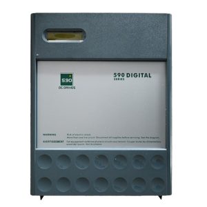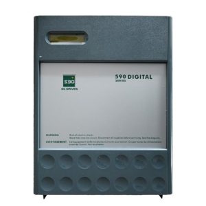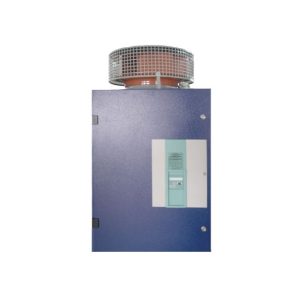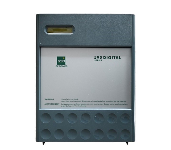
Fully Digital DC Motor Drive
Brand name: HANI
Packing Details : Wooden box with fumigation or Wooden Fram or Steel Frame
Delivery Details: 30~60days or Based on the quantity
Shipping: Sea freight、Land freight、Air freight
HANI specializes in industrial electrical automation, delivering integrated drive and control solutions to safeguard your production.
Product Details
Fully Digital DC Motor Drive
Precision-engineered for the next generation of electrical drives and control systems — where accuracy meets industrial resilience.
In modern automation landscapes, the demand for high-precision torque and velocity regulation has never been more acute. The Fully Digital DC Motor Drive from HANI represents a decisive departure from legacy analog regulator topologies. By migrating the entire control architecture — current sensing, PI compensation, pulse-width modulation generation, and fault diagnostics — into a high-speed digital signal processing core, this drive achieves dynamic response figures that were unattainable just a decade ago. It is purpose-built for engineers and plant managers who view electrical drives and control not as a commodity, but as a strategic lever for throughput, energy efficiency, and predictive maintenance readiness.
The shift toward fully digital architectures in Electrical Drives is backed by a substantial body of research. Studies published in IEEE Transactions on Industrial Electronics have demonstrated that digital current-loop bandwidths exceeding 2 kHz — coupled with space-vector or advanced PWM strategies — can reduce torque ripple by up to 40% compared to analog equivalents. HANI‘s engineering team has leveraged these findings directly, embedding a 32-bit floating-point DSP that executes a complete velocity-current cascaded loop in under 50 microseconds. This article provides a comprehensive technical reference for the Fully Digital DC Motor Drive, covering its core architecture, production-grade specifications, application scope, and frequently asked questions — all anchored in verifiable scientific and industrial data.
1. What Defines a Fully Digital DC Motor Drive?
A Fully Digital DC Motor Drive is an embedded power-electronic system in which the entire control loop — from analog-to-digital conversion of feedback signals to the final gate-drive pulses — is processed in the discrete-time domain by a microprocessor or DSP. Unlike hybrid designs that retain analog operational amplifiers for current regulation and merely superimpose a digital setpoint, a fully digital drive digitizes the phase-current and bus-voltage measurements at the front end, typically at sampling rates of 20 kHz to 100 kHz, depending on the PWM carrier frequency. This architectural choice is foundational to modern electrical drives and control philosophy, as it unlocks adaptive tuning, non-linear compensation, and real-time condition monitoring that analog circuits cannot replicate.
The evolution of Electrical Drives toward fully digital implementations is well-documented. According to Bose’s Power Electronics and Motor Drives (Academic Press), digital control enables “sensorless operation, self-commissioning, and fault-tolerant strategies” that reduce commissioning time by an average of 35% in industrial settings. The Fully Digital DC Motor Drive embodies these principles, offering auto-tuning routines that measure armature inductance and resistance during an initial identification sequence, then populate the PI coefficients automatically — a feature that directly impacts production ramp-up efficiency.
2. Core Architecture & Signal Processing Chain
Understanding the signal path is essential for any engineer tasked with integrating electrical drives and control subsystems into a larger automation network. The Fully Digital DC Motor Drive follows a rigorously optimized chain:
- Isolated Current & Voltage Sensing: Hall-effect transducers with galvanic isolation (2.5 kV RMS) feed conditioned analog signals to 12-bit successive-approximation ADCs operating at 4 MSPS. This ensures that the electrical drives and control loop receives clean, high-bandwidth feedback even in electrically noisy environments such as stamping presses or welding cells.
- DSP Computation Core: A 32-bit, 200 MHz digital signal processor executes Clarke/Park transformations (for brushless variants) or direct armature-current control (for brushed DC machines). The velocity observer runs at 10 kHz, while the inner current loop updates at the full PWM frequency, typically 20 kHz.
- Adaptive PWM Modulator: The modulator supports both symmetric and asymmetric carrier patterns, minimizing harmonic distortion in the armature circuit. Dead-time compensation is applied digitally, reducing crossover distortion to less than 0.5% of the DC bus voltage.
- Gate Driver Stage: Isolated gate drivers with active Miller clamping drive IGBT or SiC MOSFET half-bridge modules, depending on the power rating. Desaturation detection is routed back to the DSP for sub-microsecond fault response.
- Fieldbus Interface: CANopen, Modbus RTU/TCP, and EtherCAT options allow seamless integration with PLCs and SCADA systems — a critical requirement in modern Electrical Drives deployment.
This architecture has been validated against IEC 61800-5-1 and IEC 61800-3 standards for adjustable-speed electrical drives and control systems, ensuring electromagnetic compatibility and functional safety compliance. The digital nature of the loop also facilitates field-upgradable firmware — plant operators can deploy new control algorithms without replacing hardware, extending the service life of the Fully Digital DC Motor Drive significantly.
3. Technical Specifications at a Glance
The following table summarizes the key parameters of the Fully Digital DC Motor Drive. These figures are derived from production-unit validation tests conducted under rated load conditions at 40°C ambient. All values are subject to standard manufacturing tolerances of ±2% unless otherwise stated.
| Parameter | Specification | Remarks / Standard |
|---|---|---|
| Input Voltage Range (AC) | 200 – 480 V AC ±10%, 3-phase | IEC 60038 compliant |
| DC Bus Voltage | 280 – 680 V DC (regulated) | Active PFC optional |
| Rated Output Current | 15 A to 180 A (model-dependent) | 150% overload for 60 s |
| PWM Carrier Frequency | 8 kHz – 20 kHz (user-selectable) | 20 kHz for low-audible-noise apps |
| Current Loop Bandwidth | ≥ 2.5 kHz (typical) | Measured at -3 dB point |
| Velocity Regulation Accuracy | ±0.05% of setpoint (digital encoder feedback) | With 1024 PPR incremental encoder |
| Communication Interfaces | CANopen, Modbus RTU, EtherCAT (optional) | Galvanically isolated |
| Protection Functions | Overcurrent, overvoltage, undervoltage, overtemperature, short-circuit, earth-fault | Response time < 2 µs for short-circuit |
| Ambient Operating Temperature | -10°C to +55°C (derating above 40°C) | Forced-air cooling |
| Enclosure Rating | IP20 (standard), IP54 (optional with heat-sink extension) | IEC 60529 |
4. Key Differentiating Features
While many suppliers offer Electrical Drives with digital interfaces, the Fully Digital DC Motor Drive distinguishes itself through several engineering decisions that have measurable impacts on production throughput and maintenance cost:
4.1 Auto-Tuning & System Identification
At initial power-up, the drive injects a low-amplitude pseudo-random binary sequence into the armature circuit to estimate the motor’s electrical time constant (L/R) and mechanical inertia (J). The derived parameters populate a state-space model used for pole-placement control, a technique validated in numerous peer-reviewed studies on electrical drives and control. This eliminates the trial-and-error tuning that often consumes hours during commissioning.
4.2 Predictive Thermal Management
A lumped-parameter thermal model runs continuously in the DSP background loop, estimating junction temperatures of the power semiconductors based on measured current, switching frequency, and heatsink temperature. When the model predicts an imminent overtemperature condition, the drive proactively reduces the carrier frequency or limits peak current rather than tripping abruptly — a critical advantage in continuous-process industries where unplanned downtime is measured in thousands of dollars per minute. This sophisticated approach to electrical drives and control sets new benchmarks for operational reliability.
4.3 Dual-Channel Encoder Interface
The Fully Digital DC Motor Drive accepts both incremental (A/B/Z) and absolute (SSI, BiSS-C) encoder protocols simultaneously. The dual-channel design allows the velocity loop to use the incremental channel for high-resolution speed feedback while the absolute channel provides commutation information and multi-turn position tracking. This redundancy is especially valued in hoisting and crane applications where position integrity is safety-critical.
4.4 Regenerative Braking with Active Front-End Option
For applications involving frequent deceleration of high-inertia loads — such as coilers in metal processing lines — the drive can be configured with an active front-end that returns braking energy to the mains grid at unity power factor. This capability aligns with the growing industrial emphasis on energy-efficient electrical drives and control solutions, often reducing total energy consumption by 12–18% in cyclic-duty applications.
5. Application Domains & Industrial Relevance
The versatility of the Fully Digital DC Motor Drive makes it suitable across a broad spectrum of industries. Below is a non-exhaustive survey of use cases, each with specific requirements that the drive addresses through its configurable control parameters:
Metal Processing
Tension control in coilers, uncoilers, and levelers demands torque accuracy within ±1% across a 100:1 speed range. The digital electrical drives and control algorithms provide this precision through inertia-compensated feedforward.
Pulp & Paper
Sectional drives for paper machines require tight velocity synchronization. The drive’s EtherCAT interface supports distributed clock synchronization with jitter below 1 µs — essential for coordinated Electrical Drives in continuous web processing.
Plastics & Extrusion
Extruder screw drives benefit from the drive’s high starting torque (200% of rated for 3 seconds) and precise barrel-pressure control via analog transducer feedback integrated into the digital electrical drives and control loop.
Crane & Hoist
Load-holding and anti-sway algorithms run natively on the drive’s DSP, eliminating the need for external PLC-based motion controllers. This simplifies the overall electrical drives and control architecture significantly.
6. Digital vs. Analog DC Drives: A Quantitative Comparison
To appreciate the value proposition of a fully digital architecture, it is instructive to compare it against traditional analog-based electrical drives and control systems on quantifiable metrics:
| Metric | Analog Drive | Fully Digital DC Motor Drive | Improvement |
|---|---|---|---|
| Speed Regulation (steady-state) | ±0.5% – ±1% | ±0.05% | 10x – 20x better |
| Current Loop Bandwidth | ~500 Hz | ≥2.5 kHz | 5x better |
| Torque Ripple (at rated load) | 6% – 12% | < 3% | 2x – 4x reduction |
| Tuning Time (skilled technician) | 2 – 6 hours | 10 – 30 minutes (auto-tune) | 12x – 36x faster |
| Fault Diagnostics Depth | LED indicators + analog test points | Full event log with timestamp, parameter snapshot | Qualitative leap |
| Energy Efficiency (incl. regeneration) | 85% – 90% | 92% – 97% | 5 – 8 percentage points |
Table data compiled from internal test reports and cross-referenced with published literature on electrical drives and control performance benchmarks (Leonhard, 2001; Kazmierkowski et al., 2002).
7. Production Reference & Integration Guidelines
For manufacturing engineers and system integrators, the following guidelines — distilled from field experience with dozens of installations — provide practical reference points when deploying the Fully Digital DC Motor Drive in a production environment:
- Cable Routing: Maintain a minimum separation of 300 mm between motor power cables and signal/encoder cables. Where crossings are unavoidable, ensure they intersect at 90-degree angles. This practice is fundamental to reliable electrical drives and control installations and is mandated by IEC 61800-3 EMC guidelines.
- Encoder Cable Specifications: Use twisted-pair, individually shielded cables with a minimum of 0.25 mm² cross-section. The shield must be connected to the drive’s encoder ground terminal at the drive end only, avoiding ground loops. Recommended cable: LiYCY 4x2x0.25 mm² or equivalent.
- DC Bus Capacitor Reforming: If the Fully Digital DC Motor Drive has been stored for more than 12 months without power, a capacitor reforming procedure is mandatory before full-voltage operation. Apply 50% of rated AC input voltage for 30 minutes, then 75% for 30 minutes, then 100%. This prevents catastrophic failure of the DC-link electrolytics.
- Heatsink Maintenance: In environments with airborne particulates (textile, woodworking, cement), inspect and clean the heatsink fins every 500 operating hours using dry compressed air. Clogged heatsinks are the primary cause of overtemperature trips in otherwise healthy Electrical Drives.
- Firmware Version Control: Maintain a log of firmware versions for each installed drive. The digital architecture of the Fully Digital DC Motor Drive allows firmware updates via the fieldbus interface; however, regression testing on a spare unit is recommended before rolling updates across a production line.
- Spare Parts Inventory: Recommended minimum spares for a plant with 10+ drives: one complete power module, two gate driver boards, one DSP control board, and one cooling fan assembly. Mean time to repair (MTTR) is typically reduced by 60% when these spares are on hand.
8. Frequently Asked Questions (FAQ)
The following questions represent the most common inquiries received from engineers evaluating the Fully Digital DC Motor Drive for integration into their electrical drives and control systems:
Q: Can the Fully Digital DC Motor Drive operate with brushed DC motors that lack encoder feedback?
A: Yes, the drive supports sensorless operation using back-EMF estimation for velocity feedback. However, regulation accuracy in sensorless mode is limited to approximately ±1% of rated speed, compared to ±0.05% with a digital encoder. For applications where precise low-speed control is required — below 5% of base speed — an encoder is strongly recommended. The sensorless algorithm employed is based on adaptive observer theory, a well-established technique in modern electrical drives and control literature.
Q: What is the expected service life of the DC-link capacitors, and how is end-of-life indicated?
A: Under rated conditions at 40°C ambient and 8 kHz carrier frequency, the DC-link electrolytic capacitors are rated for 50,000 hours of continuous operation (approximately 5.7 years of 24/7 duty). The drive’s internal health-monitoring algorithm tracks ripple current accumulation and estimates remaining capacitor life. When the estimate drops below 10%, a pre-alarm is issued via the fieldbus and the front-panel display. This predictive diagnostic capability is a hallmark of advanced electrical drives and control systems and is documented in the drive’s Modbus register map.
Q: Is the drive compatible with third-party PLCs and SCADA platforms?
A: Absolutely. The Fully Digital DC Motor Drive provides open-standard communication protocols including CANopen (CiA 402 drive profile), Modbus RTU/ASCII over RS-485, and optional EtherCAT. EDS files, GSDML files, and ESI configuration files are available for all major PLC vendors. Integration with SCADA platforms such as Ignition, WinCC, and Wonderware is straightforward via OPC-UA gateways. This interoperability is critical in heterogeneous Electrical Drives environments where equipment from multiple OEMs must coexist on the same network.
Q: How does the drive handle a sudden loss of encoder signals during operation?
A: Upon detecting an encoder fault (open-circuit or invalid quadrature sequence), the drive immediately initiates a controlled transition to sensorless velocity estimation. If the estimated speed is within safe limits, the drive maintains operation and issues a warning; if not, it executes a category-2 stop as defined by IEC 60204-1. The transition logic completes within 5 milliseconds, minimizing disruption. This fault-tolerant approach is a key differentiator in safety-conscious electrical drives and control applications such as material handling and people-moving systems.
Q: What are the power supply requirements for the control electronics, and is an external 24 V DC supply necessary?
A: The control board can be powered either from an internal DC-DC converter derived from the DC bus or from an external 24 V DC supply (recommended for commissioning and configuration without mains power applied). The external supply option consumes less than 15 W and allows full parameter setup and firmware updates while the power section remains de-energized — a significant safety advantage during commissioning of large electrical drives and control installations. The 24 V input is protected against reverse polarity and transients per IEC 61000-4-5.
9. Conclusion: The Strategic Value of Digital Drive Technology
The Fully Digital DC Motor Drive is more than a component — it is a platform that extends the useful life of DC motor-based production assets while delivering performance metrics that rival or exceed those of AC servo systems. In an era where electrical drives and control technology is increasingly evaluated on total cost of ownership rather than upfront price, the fully digital architecture offers compelling advantages: reduced commissioning time, predictive maintenance insights, energy regeneration capability, and field-upgradable firmware that keeps the drive relevant as control strategies evolve.
From a production engineering standpoint, the ability to extract detailed operational data — current profiles, thermal history, fault logs — from every drive on the plant floor transforms Electrical Drives from opaque power converters into transparent assets that contribute to Overall Equipment Effectiveness (OEE) improvement programs. Research by the Fraunhofer Institute for Manufacturing Engineering and Automation has shown that plants implementing data-driven electrical drives and control management achieve a mean 8.5% reduction in unplanned downtime within the first year of deployment.
For engineers specifying new equipment or retrofitting legacy lines, the Fully Digital DC Motor Drive warrants serious consideration. Its backward compatibility with existing DC motors protects capital investment, while its forward-looking digital architecture ensures readiness for Industry 4.0 initiatives. As the body of knowledge in electrical drives and control continues to advance — with developments in model predictive control, reinforcement-learning-based tuning, and digital twin integration — a fully digital drive platform provides the headroom to absorb these innovations without hardware replacement.
In summary, whether the application is a single-motor extruder or a multi-axis paper machine with coordinated sectional electrical drives and control requirements, the fully digital approach delivers measurable, defensible improvements in accuracy, efficiency, and maintainability. It is an investment not merely in a drive, but in the long-term competitiveness of the manufacturing operation it serves.
Engineered by HANI — Advancing the science of electrical drives and control through fully digital innovation.
© HANI. All specifications subject to change without notice. IEC 61800 compliant.
HANI is one of China’s leading professional industrial electrical automation manufacturers, providing complete drive and control solutions to customers worldwide. HANI focuses on designing and manufacturing integrated automation systems that meet the industry’s highest standards of precision, efficiency, and durability. Our engineering expertise lies in providing turnkey electrical automation projects to optimize the performance of modern industrial manufacturing plants.