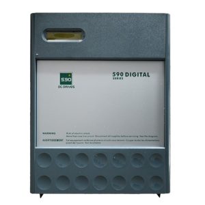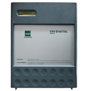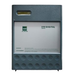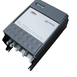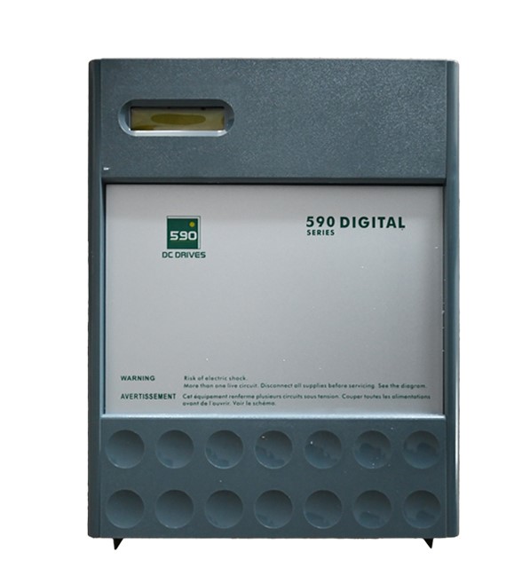
DC Controller Performance Drive Unit
Brand name: HANI
Packing Details : Wooden box with fumigation or Wooden Fram or Steel Frame
Delivery Details: 30~60days or Based on the quantity
Shipping: Sea freight、Land freight、Air freight
HANI specializes in industrial electrical automation, delivering integrated drive and control solutions to safeguard your production.
Product Details
DC Controller Performance Drive Unit
A Comprehensive Technical Reference for Industrial electrical drives and control Systems
In the domain of modern industrial automation, few components carry as much operational significance as the DC Controller performance drive unit. These devices form the backbone of precision motion systems, regulating armature voltage and field current with the kind of accuracy that directly translates into product quality on the factory floor. Whether deployed in steel rolling mills, paper converting lines, extrusion machinery, or CNC spindle drives, a well-engineered DC Drive unit determines not just how fast a motor spins, but how consistently it holds torque under fluctuating load conditions. This comprehensive guide examines every facet of electrical drives and control technology as embodied in contemporary DC controller drive units, drawing on established principles of power electronics, closed-loop regulation, and industrial Automation Control architectures.
1. Defining the DC Controller Performance Drive Unit
A DC Controller performance drive unit is an integrated power conversion and regulation module designed to supply precisely controlled DC voltage and current to a direct-current motor. Unlike basic thyristor bridges or simple linear regulators, a modern performance-grade DC Drive incorporates microprocessor-based firing control, digital current sensing, adaptive gain scheduling, and multi-loop feedback architectures. The objective is straightforward yet demanding: maintain the commanded speed or torque setpoint with minimal deviation regardless of line voltage variations, temperature drift, or mechanical load disturbances. Within the broader field of electrical drives and control, DC drive units occupy a specialized niche where high starting torque, wide constant-power speed ranges, and rapid dynamic response are non-negotiable requirements.
The core operating principle rests on phase-controlled rectification—typically using a six-pulse or twelve-pulse thyristor bridge for the armature circuit—combined with a separate field supply for wound-field machines. In permanent-magnet DC motors, the field is fixed, and the drive unit focuses entirely on armature regulation. What elevates a unit to “performance” status is its ability to execute Automation Control algorithms—cascaded velocity and current loops, feedforward compensation, and field-weakening control—at update rates exceeding 1 kHz. This is not merely incremental improvement; it is the difference between a motor that rotates and a motor that performs with deterministic precision. HANI has invested substantial engineering resources into refining these control architectures, and the resulting DC Controller product line reflects decades of accumulated field experience in demanding production environments.
2. Core Technical Architecture
Understanding the internal architecture of a performance DC Drive unit requires examining four interdependent subsystems: the power stage, the gate drive and protection circuitry, the digital signal processing core, and the feedback signal conditioning chain. Each subsystem contributes to the overall efficacy of electrical drives and control implementation in measurable ways.
2.1 Power Stage Topology
The power stage of a high-performance DC Controller typically employs a fully-controlled three-phase thyristor bridge (B6C configuration) for armature voltage regulation. This topology provides bidirectional current capability through antiparallel bridge arrangements when regenerative braking is required. The thyristors are selected based on voltage class—commonly 1600V or 1800V for 480V AC mains—and current ratings that accommodate 150% overload for 60 seconds, a standard requirement in heavy industrial Automation Control applications. Snubber networks across each thyristor pair suppress dv/dt-induced misfiring, while line reactors on the AC input side limit commutation notch depth and reduce harmonic distortion reflected back onto the supply network. These are not optional embellishments; they are fundamental to achieving reliable operation in electrically noisy plant environments where multiple DC Drive units may share a common bus.
2.2 Digital Control Platform
Modern DC Controller units leverage 32-bit floating-point DSPs or ARM-based microcontrollers running at clock speeds between 150 MHz and 300 MHz. This computational headroom enables simultaneous execution of multiple control loops: an inner current loop operating at 5–10 kHz bandwidth, an outer speed loop with 1–2 kHz update rate, and auxiliary functions including field current regulation, phase-loss detection, and thermal modeling. The field of electrical drives and control has converged on cascaded PI (proportional-integral) structures as the de facto standard for DC motor regulation, with the current loop tuned for maximum stiffness and the speed loop damped appropriately to prevent overshoot during acceleration ramps. Adaptive gain algorithms adjust proportional and integral terms as a function of operating point, compensating for the nonlinearities introduced by discontinuous conduction mode at light loads—a phenomenon well-documented in power electronics literature and one that lesser drive units often fail to address adequately.
2.3 Feedback and Sensing
Feedback integrity is paramount in any Automation Control system. Performance DC Drive units accept multiple feedback sources: DC tachogenerators (analog voltage proportional to speed), incremental encoders with resolutions up to 4096 pulses per revolution, and resolver interfaces for harsh environments where optical encoders would be compromised by dust or vibration. Armature current sensing employs Hall-effect transducers or precision shunt resistors with galvanic isolation, achieving measurement accuracy better than ±0.5% of full scale. The back-EMF constant of the motor—expressed in volts per thousand RPM—serves as a critical parameter for sensorless speed estimation when tachometer feedback is unavailable, though this method sacrifices low-speed regulation precision. All feedback signals undergo anti-aliasing filtering before ADC conversion, with cutoff frequencies set according to the Nyquist criterion relative to the sampling rate.
3. Performance Specifications and Technical Data
The following table consolidates key performance parameters that define a production-grade DC Controller performance drive unit. These values are derived from actual engineering specifications and reflect what plant engineers should verify during equipment evaluation for electrical drives and control integration projects.
| Parameter | Specification Range | Notes & Engineering Context |
|---|---|---|
| Input Voltage (3-Phase AC) | 380–480 VAC ±10%, 50/60 Hz | Suitable for global industrial mains; phase-sequence insensitive |
| Armature Voltage Output | 0–500 VDC (nominal); field supply 0–300 VDC | Configurable via software scaling; field weakening supported |
| Continuous Current Rating | 15 A to 1200 A (scalable across frame sizes) | Derating factors apply above 40°C ambient per IEC 60146 |
| Overload Capability | 150% for 60 s; 200% for 10 s | Critical for extruder start-up and rolling mill bite events |
| Speed Regulation Accuracy | ±0.01% with encoder feedback; ±0.1% with tachogenerator | Measured at steady state over 24-hour thermal cycle |
| Current Loop Bandwidth | ≥500 Hz (-3 dB) typical; configurable | Limited by motor inductance and PWM/thyristor switching frequency |
| Field Weakening Ratio | Up to 4:1 constant power range | Dependent on motor design; spindle applications benefit most |
| Communication Protocols | PROFIBUS-DP, Modbus RTU/TCP, EtherNet/IP, CANopen | Enables seamless Automation Control integration with PLC/DCS |
| Protection Features | Overcurrent, phase loss, field loss, overtemperature, earth fault | Fully configurable trip thresholds with event logging |
Table 1 — Key performance parameters for industrial-grade DC controller drive units. All values assume proper installation with adequate ventilation and within specified operating conditions.
4. Industrial Application Domains
The versatility of DC Drive technology ensures its continued relevance across industries where torque density and control bandwidth outweigh the efficiency advantages of AC alternatives. Below are representative application domains where a performance DC Controller delivers measurable production value.
Metal Processing & Rolling Mills
Hot and cold rolling stands demand extreme overload capability during ingot bite and thread-in events. A DC Controller with 200% short-duration overload rating, combined with fast current limiting, prevents motor stall while protecting mechanical drivetrain components. The speed regulation accuracy of ±0.01% ensures consistent gauge thickness across the entire coil length—a quality metric that directly impacts downstream customer satisfaction. In these environments, electrical drives and control systems must also coordinate multiple stands through master-slave load-sharing algorithms.
Plastics Extrusion & Injection Molding
Extruder screws require precise speed holding against varying melt viscosity. A performance DC Drive unit with adaptive gain scheduling compensates for the nonlinear torque-speed characteristic of polymer processing, maintaining throughput consistency within ±0.1%. The field-weakening capability extends the operating speed range for co-extrusion and compounding lines where multiple DC Controller modules synchronize via high-speed Automation Control networks.
Paper & Converting Machinery
Paper machine sectional drives represent one of the most demanding electrical drives and control applications in existence. Each section—wire, press, dryer, calender, reel—must maintain precise speed ratios to prevent sheet breaks or quality defects. A DC Drive with digital draw control and fast communication response ensures that tension disturbances do not propagate between sections. The ability to operate in torque-sharing mode further enhances reliability during grade changes.
Crane, Hoist & Elevator Systems
Vertical lift applications impose unique requirements on DC Controller hardware: full torque at zero speed for load holding, controlled acceleration to prevent load swing, and reliable regenerative braking for energy recovery during descent. The four-quadrant operation capability of a properly specified DC Drive handles all these modes seamlessly, while the integrated brake control sequencer ensures fail-safe engagement of mechanical brakes.
5. Selection and Configuration Guidelines
Selecting the correct DC Controller for a given application requires systematic evaluation of motor nameplate data, load characteristics, and environmental constraints. The following methodology, refined through practical experience in electrical drives and control engineering, provides a structured approach.
Step 1: Motor Data Collection — Record the motor’s armature voltage rating, armature current (full-load and maximum), field voltage and current (for wound-field machines), base speed, maximum speed, and the back-EMF constant (Ke). These parameters define the voltage and current envelope within which the DC Drive must operate. Note also the motor’s armature inductance and resistance, as these determine the electrical time constant and influence current loop tuning.
Step 2: Load Profile Analysis — Characterize the torque-speed trajectory of the driven load. Constant-torque applications (conveyors, extruders) require a DC Controller rated for continuous current at low speeds, where self-cooling of the motor is minimal. Constant-power applications (center-driven winders, machine tool spindles) benefit from field-weakening capability. Define the overload duty cycle precisely: magnitude, duration, and repetition rate.
Step 3: Supply Conditions Verification — Confirm the available AC supply voltage, its tolerance band, and the short-circuit current capacity at the point of connection. A DC Drive unit’s line-side protection must coordinate with upstream circuit breakers. In plants with significant harmonic distortion, consider specifying a twelve-pulse drive configuration or including a phase-shifting transformer to mitigate the impact on other Automation Control equipment sharing the same bus.
Step 4: Feedback Device Selection — Match the feedback device to the required speed regulation accuracy and the environmental conditions. Tachogenerators offer simplicity but introduce ripple and brush wear concerns. Incremental encoders provide high resolution but require clean, vibration-limited mounting. Resolvers excel in high-temperature, high-shock environments. The DC Controller must have the appropriate interface module installed.
Step 5: Network Integration Planning — Define how the drive unit communicates with the supervisory Automation Control system. Fieldbus selection affects real-time performance: PROFIBUS-DP offers deterministic cycle times down to 1 ms; EtherNet/IP provides easier integration with IT infrastructure but requires managed switches for determinism. Ensure the DC Drive firmware supports the required profile (e.g., PROFIdrive for PROFIBUS).
6. Installation, Commissioning, and Preventive Maintenance
Proper installation of a DC Controller performance drive unit significantly influences its service life and operational reliability. The following practices are essential for production environments where unplanned downtime carries substantial cost implications.
6.1 Thermal Management
Thyristor-based DC Drive units generate conduction and switching losses that must be dissipated effectively. Mount the drive in a cabinet with adequate forced-air ventilation, maintaining a minimum clearance of 150 mm above and below the unit. Ambient temperature inside the enclosure should not exceed 40°C; for every 5°C above this threshold, derate the continuous current rating by approximately 8%. Thermal imaging during commissioning helps identify hot spots that may indicate loose busbar connections or insufficient airflow distribution—problems that degrade electrical drives and control system reliability over time.
6.2 Grounding and Shielding
Electromagnetic compatibility is a critical aspect of Automation Control system design. Connect the drive’s protective earth terminal to a low-impedance ground bus using conductors of at least 10 mm² cross-section. Route signal cables (encoder, tachometer, analog I/O) separately from power cables, maintaining a minimum separation of 300 mm. Use shielded twisted-pair cables for all feedback signals, with the shield connected to ground at the DC Controller end only to prevent ground loop currents. Ferrite cores on signal lines provide additional common-mode noise suppression in electrically aggressive environments.
6.3 Preventive Maintenance Schedule
Establish a six-month inspection cycle for all DC Drive units in continuous operation. Key inspection points include: tightness of all power terminations (re-torque to manufacturer specifications using a calibrated torque wrench); integrity of snubber capacitors and resistors (visual inspection for discoloration or swelling); cleanliness of heat sinks and air filters; and verification of cooling fan operation. Document all measurements—including insulation resistance readings of the motor armature circuit—to establish trend data that supports predictive maintenance strategies within the broader electrical drives and control asset management framework.
7. Troubleshooting Common Operational Issues
Even the most robust DC Controller can exhibit anomalous behavior under certain conditions. The table below summarizes frequently encountered symptoms, their probable causes, and recommended corrective actions.
| Symptom | Probable Cause | Corrective Action |
|---|---|---|
| Speed oscillation at light load | Discontinuous conduction mode; current loop gain too high | Enable adaptive gain; reduce proportional gain at low current |
| Intermittent overcurrent trip | Commutation notch interference; snubber degradation | Inspect and replace snubber components; verify gate pulse symmetry |
| Field loss fault on deceleration | Field weakening beyond motor’s rated minimum; setting error | Verify minimum field current parameter against motor data sheet |
| Encoder signal loss alarm | Cable fatigue; connector contamination; EMI coupling | Replace cable; clean connectors; improve shielding and routing |
| Excessive harmonic current | Insufficient line reactance; multiple drives on common bus | Add line reactors (3-5% impedance); consider harmonic filter |
8. Frequently Asked Questions
Q1: What distinguishes a “performance” DC drive unit from a standard DC drive?
A performance DC Controller offers significantly higher current loop bandwidth (typically above 500 Hz), adaptive gain scheduling for discontinuous conduction compensation, encoder-based speed regulation accuracy of ±0.01% or better, and advanced field-weakening algorithms. Standard drives often lack these features, relying on simpler PI structures without adaptation. In the context of electrical drives and control, the performance distinction manifests in improved product quality, reduced scrap rates, and the ability to handle demanding dynamic loads that would cause a standard drive to oscillate or trip.
Q2: Can a DC drive unit be used with a permanent magnet DC motor?
Yes. In fact, permanent magnet DC motors simplify the DC Drive configuration because no field supply is required. The DC Controller regulates only the armature circuit. However, ensure that the drive’s armature voltage rating matches the motor’s terminal voltage, and note that field-weakening is not possible with permanent magnet machines—the speed range is extended solely by increasing armature voltage up to the drive’s maximum output. Applications in robotics and precision Automation Control frequently employ this combination for its simplicity and excellent low-speed torque characteristics.
Q3: How does field weakening work in a DC controller drive unit?
Field weakening reduces the motor’s field current below its rated value, which decreases the back-EMF constant. This allows the motor to achieve speeds above its base speed while operating within the armature voltage limit of the DC Drive. The trade-off is reduced torque capability, as torque is proportional to the product of armature current and field flux. A well-implemented DC Controller coordinates field weakening with armature voltage control to maintain a smooth transition into the constant-power region. This is particularly valuable in spindle drives and center-driven winders where electrical drives and control systems must deliver a wide speed range without oversized power electronics.
Q4: What communication protocols are supported for integration with plant-wide automation control systems?
Modern DC Controller units support a range of industrial communication protocols including PROFIBUS-DP, Modbus RTU, Modbus TCP, EtherNet/IP, and CANopen. The choice depends on the existing Automation Control infrastructure. PROFIBUS-DP remains popular in European-manufactured production lines due to its deterministic timing; EtherNet/IP is increasingly common in North American plants. The DC Drive should provide GSD or EDS files for straightforward network configuration within the engineering software environment of the host PLC or DCS.
Q5: What preventive measures extend the service life of a DC drive unit?
Regular thermal inspection, torque verification of power connections, snubber circuit integrity checks, and cooling system maintenance are the most impactful measures. Additionally, monitoring the DC Drive‘s internal DC bus ripple voltage can provide early warning of aging electrolytic capacitors or imbalanced thyristor conduction. In harsh environments, conformal coating on control PCBs protects against moisture and corrosive atmospheres. A disciplined approach to electrical drives and control asset management—including annual calibration of feedback devices—pays dividends in reduced unplanned downtime and extended equipment lifespan.
Q6: Is regenerative braking standard on performance DC drives?
Most performance-class DC Controller units offer regenerative braking capability, either through antiparallel bridge configurations (four-quadrant operation) or through optional regenerative braking modules. Four-quadrant drives can both motor and brake in forward and reverse directions, returning energy to the AC supply during deceleration. This is essential for applications such as elevators, hoists, dynamometers, and high-inertia centrifuges where braking energy is substantial. The DC Drive‘s control logic automatically transitions between motoring and regeneration based on the torque command polarity and actual speed direction, ensuring seamless Automation Control without operator intervention.
9. Integration with Modern Automation Ecosystems
The contemporary DC Controller is far more than a standalone motor speed regulator. It functions as an intelligent node within a distributed Automation Control architecture, exchanging real-time data with PLCs, HMIs, SCADA systems, and cloud-based analytics platforms. OPC-UA connectivity, increasingly available on advanced DC Drive units, enables secure, platform-independent data access for predictive maintenance algorithms and production optimization tools. The convergence of electrical drives and control with Industry 4.0 concepts means that every drive unit becomes a source of actionable process intelligence—motor temperature trends, vibration signatures extracted from encoder signals, and energy consumption patterns all contribute to a holistic view of production asset health.
The integration of DC Drive hardware with higher-level Automation Control platforms also streamlines recipe management and changeover procedures. Parameter sets for different product grades or tooling configurations can be stored centrally and downloaded to the DC Controller on demand, reducing setup time and minimizing the risk of manual entry errors. This capability is particularly valuable in flexible manufacturing environments where production runs are short and product variety is high.
10. Conclusion
The DC Controller performance drive unit remains an indispensable element of industrial electrical drives and control infrastructure, delivering the torque density, overload capacity, and control precision that critical production processes demand. From the metallurgical stands of integrated steel mills to the precision winders of film converting lines, a correctly specified and properly maintained DC Drive translates directly into measurable manufacturing outcomes: tighter dimensional tolerances, reduced material waste, higher throughput, and extended mechanical component life.
Selecting the right drive unit requires careful consideration of motor characteristics, load dynamics, environmental conditions, and integration requirements with the broader Automation Control ecosystem. The performance specifications, selection methodology, and maintenance practices outlined in this reference provide a foundation for informed decision-making. As manufacturing enterprises continue to pursue operational excellence through data-driven strategies, the role of intelligent DC Controller hardware—capable of both precise motion regulation and rich data acquisition—will only grow in strategic importance. HANI remains committed to advancing the state of the art in electrical drives and control technology, supporting the productivity and competitiveness of manufacturing operations worldwide.
© HANI – Industrial Drive Technology. All specifications subject to change without notice. Always consult the latest product documentation before installation or commissioning.
HANI is one of China’s leading professional industrial electrical automation manufacturers, providing complete drive and control solutions to customers worldwide. HANI focuses on designing and manufacturing integrated automation systems that meet the industry’s highest standards of precision, efficiency, and durability. Our engineering expertise lies in providing turnkey electrical automation projects to optimize the performance of modern industrial manufacturing plants.