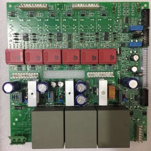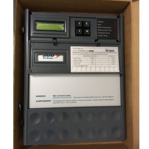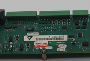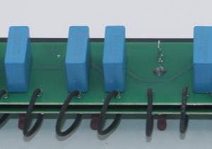
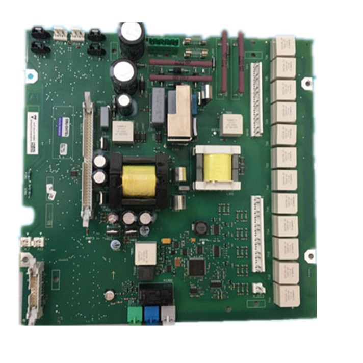
Siemens 6RA80 Power Board C98043-A7105-L1 – Essential Spare for Automation Control Panel
Brand name: HANI
Packing Details : Wooden box with fumigation or Wooden Fram or Steel Frame
Delivery Details: 30~60days or Based on the quantity
Shipping: Sea freight、Land freight、Air freight
HANI specializes in industrial electrical automation, delivering integrated drive and control solutions to safeguard your production.
Product Details
Industrial Automation Products · DC Drive Spare Parts
Siemens 6RA80 Power Board C98043-A7105-L1 – Essential Spare for Automation Control Panel
The Siemens C98043-A7105-L1 Power Board is a precision-engineered power interface module at the heart of the SINAMICS DCM 6RA80 DC drive system. Serving as the critical bridge between incoming AC mains and the internal control electronics, this board performs multi-stage voltage conversion, line synchronization, thyristor firing-pulse generation, and comprehensive circuit protection. For industrial facilities relying on DC motor-driven production lines—rolling mills, paper machines, extruders, cranes, and hoists—stocking an authentic Siemens 6RA80 Power Board as a spare is not optional; it is essential risk management. HANI, a trusted supplier of industrial automation products, ensures genuine Siemens DC Drive Spare Parts including the C98043-A7105-L1 reach maintenance teams without the delays that can bring an entire shift to a halt.
Key Facts at a Glance: Siemens C98043-A7105-L1
| Parameter | Specification / Detail |
|---|---|
| Siemens Part Number | C98043-A7105-L1 (variant suffixes -L1-8, -L4-8 for thyristor blocking voltage calculation)[reference:0] |
| Compatible Drive Family | Siemens SINAMICS DCM 6RA80 (SIMOREG DC-Master lineage) |
| Voltage Class | Power Interface 400 – 600 V AC (C98043-A7105 series); sister module C98043-A7106 covers 690 – 950 V[reference:1] |
| Electronics Power Supply Input | 2-ph. 380 V AC (–25%) to 480 V (+10%), In=1 A; or 1-ph. 190 V (–25%) to 240 V (+10%), In=2 A[reference:2] |
| Internal Output Rails | +5 V DC (microprocessor core), +12 V DC, +24 V DC (load circuits)[reference:3] |
| Internal Protection | Fuses F200, F201 on module; external protection max. 6 A, characteristic C recommended[reference:4] |
| Key Functions | Firing pulse generation for armature & field thyristors; voltage synchronization; closed-loop/open-loop control computation; relay output for line contactor[reference:5] |
| Terminals | XP1 (5U1, 5W1, 5N1) for electronics supply; XR1 (109/110) relay for line contactor; XS1 (105/106) E-STOP; XT1 (103/104) analog tachometer[reference:6] |
| Quadrant Operation | 2Q and 4Q (module variant dependent)[reference:7] |
| Standards Compliance | IEC, EN, DIN, VDE, UL, cULus, NEMA, UL 508 C, GOST; EMC per IEC 61800-3[reference:8] |
1. The Power Board‘s Role in the 6RA80 Ecosystem
Within every Siemens 6RA80 DC converter cabinet, the C98043-A7105-L1 Power Board occupies a central position in the modular architecture. The SINAMICS DCM distributes its functionality across distinct plug-in modules: the CUD (Control Unit DC), the power interface module, the field module, and the power unit. The power interface module—designated by part numbers C98043-A7105 (400–600 V class) or C98043-A7106 (690–950 V class)—is responsible for generating precisely timed firing pulses to the thyristors in both the armature and field power sections, while simultaneously computing all open-loop and closed-loop control functions[reference:9]. Without a functioning Siemens 6RA80 Power Board, the drive cannot synchronize to the line voltage, cannot fire its SCR bridges, and therefore cannot deliver any controlled DC output to the motor.
From a production-engineering standpoint, this means that a single failed power interface board renders an entire drive unit inoperative. For continuous-process industries—steel rolling, paper calendering, cement kiln drives—that translates directly into unplanned downtime measured in thousands of dollars per hour. Keeping a tested, genuine C98043-A7105-L1 on the shelf is among the most cost-effective reliability investments a plant can make.
1.1 Architecture: Where the Board Fits
The standard SINAMICS DC Master configuration interconnects at least three key modules: the Standard CUD left (C98043-A7100-L1), the Power Interface (C98043-A7105-L4 or equivalent variant), and the Field Supply (C98043-A7115-L12). Together these form a complete drive control set[reference:10]. The power interface module acts as the nerve center that bridges the digital control world of the CUD with the high-power semiconductor world of the thyristor stacks. It performs:
- Line voltage measurement for armature and field circuits, used to synchronize gating pulses to the correct phase angle of the incoming three-phase supply;
- Firing pulse generation with the correct timing sequence (six-pulse B6C or twelve-pulse configurations), controlling the conduction angle of each thyristor in the rectifier bridge;
- Analog tachometer signal conditioning (Terminals XT1-103/104, ±270 V input range, 159 kΩ input resistance, ±14-bit resolution) for legacy speed feedback applications[reference:11];
- Safety chain integration via the E-STOP input (XS1-105/106) and the potential-free relay output for the main line contactor (XR1-109/110), rated ≤250 V AC, 4 A (cosφ=1)[reference:12].
2. Power-Up Sequence: How the C98043-A7105-L1 Initializes
Understanding the internal startup logic of this Siemens 6RA80 Power Board is invaluable for troubleshooting. The sequence is methodical and backed by the board‘s physical design, not marketing language:
| Step | Action | Electrical / Physical Detail |
|---|---|---|
| 1 | AC input applied to electronics supply terminals (5U1 / 5W1 / 5N1) | 400 V or 230 V configuration; line voltage passes through anti-interference filter to remove conducted EMI[reference:13] |
| 2 | Standby (auxiliary) supply starts first | Generates +5 V DC to power the microprocessor system on the main circuit board[reference:14] |
| 3 | Rectification, PFC inductor, filtering → 300 V DC rail | 300 V DC delivered to standby supply circuit; +5 V output established[reference:15] |
| 4 | CPU reads boot data, asserts high-level power-on signal | Signal routed via connector Pin 1 to digital board CPU; Pin 2 carries switching control voltage back to the power board[reference:16] |
| 5 | PFC oscillator starts; boost converter generates 400 V PFC rail | High-frequency square-wave pulses drive PFC MOSFET; flyback pulse across PFC inductor rectified and filtered to steady 400 V DC[reference:17] |
| 6 | PFC voltage detection circuit confirms 400 V threshold | Upon confirmation, main SMPS oscillator enabled; high-frequency pulses drive main switching transformer[reference:18] |
| 7 | Main transformer secondary outputs rectified & filtered | +12 V DC and +24 V DC rails delivered to load circuits; board fully operational[reference:19] |
This seven-step cascade explains why the C98043-A7105-L1 cannot be substituted with a generic SMPS module. The sequence depends on precise timing between the PFC stage, the CPU handshake, and the main converter stage—all of which are calibrated to the SINAMICS DCM firmware during factory testing.
2.1 Wiring Configurations for Electronics Supply
The electronics power supply input supports two wiring configurations depending on the available auxiliary voltage in the control panel:
- 400 V configuration: Connect 2-phase AC to terminals 5U1 and 5W1; leave 5N1 open. Internal fuses F200 and F201 (on the module itself) provide primary-side protection[reference:20].
- 230 V configuration: Bridge 5U1 and 5W1 together, then connect single-phase AC between the bridged point and 5N1. This doubles the input current (In = 2 A, with –35% tolerance for 1 minute)[reference:21].
A common field wiring mistake—connecting 380 V directly between 5U1 and 5N1 in the 230 V configuration—has been documented by service engineers and will instantly destroy the input stage. Always verify the terminal arrangement according to the schematic inside the drive enclosure before powering up a newly installed Siemens 6RA80 Power Board[reference:22].
3. DC Drive Spare Parts Strategy: Why the C98043-A7105-L1 Belongs in Every Critical Spares Inventory
The SINAMICS DCM 6RA80 family spans a power range from 6.3 kW to 2,508 kW, with rated DC currents from 15 A to 4,000 A and supply voltages from 400 V to 950 V AC[reference:23]. Within every drive in this range, regardless of frame size, the power interface module—either the C98043-A7105-L1 (400–600 V) or its 690–950 V counterpart—is a single point of failure. Unlike the CUD or the field module, the power interface board has no redundant backup within a single-drive configuration unless a twelve-pulse parallel topology is employed (in which case two complete drive sets operate in master-slave mode)[reference:24].
Industry data from steel mill drive upgrades shows that when aging SIMOREG 6RA70 systems are replaced with new Siemens 6RA80 drives, the power interface module is one of the first components that maintenance planners specify as a mandatory spare[reference:25]. The rationale is clear: the 6RA70 platform is discontinued by Siemens, and key spare parts are no longer available from the OEM, making proactive migration to 6RA80 and stocking of critical DC Drive Spare Parts a business necessity[reference:26].
3.1 Spare Parts Complementary to the C98043-A7105-L1
| Module | Siemens Part Number | Function |
|---|---|---|
| Power Interface Module | C98043-A7105-L1 (400–600 V) | Firing pulse generation, control computation, line sync |
| Standard CUD (left) | C98043-A7100-L1 | Main control unit, PROFIBUS/PROFINET interface |
| Field Supply Module | C98043-A7115-L12 | Controlled field excitation for DC motor field winding |
| Allocation Board | C98043-A7126 | Terminal interconnection; houses device EEPROM |
| Surge Absorbing Capacitor Circuit | (Integral to power unit) | RC snubber network to protect thyristors from dv/dt transients |
A fault in the surge absorbing capacitor circuit can lead to thyristor failure from overvoltage[reference:27]. When replacing the power interface module on a drive that has experienced a thyristor short-circuit event, inspecting the snubber capacitors and RC elements is a mandatory prerequisite to avoid destroying the new C98043-A7105-L1.
4. Module Selection, Variant Compatibility & Firmware Dependency
Not every C98043-A7105-L1 is interchangeable without careful variant verification. The part number structure C98043-A7105-Lx contains a critical suffix: “x” designates the module variant for 2Q (two-quadrant) or 4Q (four-quadrant) operation, and also depends on the rated voltage of the specific SINAMICS DCM unit it is installed in[reference:28]. Installing a 2Q-variant power interface board into a 4Q drive will result in immediate fault conditions because the gating logic for the reversing bridge cannot be executed.
4.1 Thyristor Blocking Voltage Calculation Feature
Starting from specific hardware revisions, the power interface module supports an advanced thyristor blocking voltage calculation function. This feature is available on the following firmware-compatible variants:
- C98043-A7105-L1-8
- C98043-A7105-L4-8
These revisions are documented in the SINAMICS DCM Operating Instructions as the minimum version required for the blocking voltage calculation to function[reference:29]. When ordering replacement DC Drive Spare Parts, always specify the complete 16-character identifier including the suffix to ensure firmware-level compatibility.
5. Diagnostic Guide for the C98043-A7105-L1
Field engineers regularly encounter several failure modes traceable to the Siemens 6RA80 Power Board. The following table consolidates practical diagnostic steps derived from service records and Siemens support documentation:
| Symptom | Probable Root Cause (Power Board) | Measurement / Verification |
|---|---|---|
| Drive powers up, no display on BOP | Internal power module failure; no +5 V or +24 V output | • Measure AC input at 5U1/5W1/5N1: 380 V ±10% (or rated ±5%)[reference:30] • Check F200, F201 on power board for continuity • Measure +5 V, +12 V, +24 V test points on output connector[reference:31] |
| Brown sticky residue around capacitors | Electrolytic capacitor dielectric leakage; aggravated by long-term storage without reforming | • Visually inspect all electrolytic capacitors on the power board for bulging tops or electrolyte seepage[reference:32] • Capacitors stored unpowered >2 years require dielectric reforming per manufacturer procedure[reference:33] |
| F30040 / F30043 / F30045 / F30050 (24 V supply faults) | Power unit 24 V under/over voltage; regulator failure on power board | • Measure 24 V DC at output rails; deviation beyond ±5% indicates regulator circuit fault[reference:34] • If +12 V rail is also unstable, the main SMPS transformer or feedback loop is suspect |
| F60062 (voltage detection communication failure) | Communication loss between CUD and voltage detection circuit on power interface board | • Test output voltage stability at ±15 V and ±24 V test points[reference:35] • Clean all sensor interface connectors; check for oxidation or loose contacts |
| Intermittent thyristor misfiring; irregular motor current | Degraded firing pulse generation; aging components in gate drive stage | • Check P50830 (thyristor test parameter) setting; run diagnostic[reference:36] • Inspect all thyristor gate-cathode connections for tightness |
5.1 Component-Level Checks (Qualified Personnel Only)
For workshops equipped to perform board-level repair, the following tests can isolate the faulty section of the C98043-A7105-L1:
- Step-down resistor test: Power down completely. Measure resistance of the step-down resistor chain against the circuit diagram reference values. Open-circuit or significant deviation (>10%) indicates aging and requires replacement[reference:37].
- Fuse verification: Check F200 and F201 for continuity. If either is blown, do not simply replace the fuse—investigate for short-circuit conditions downstream (shorted MOSFET, shorted diode, or saturated transformer winding)[reference:38].
- Capacitor visual and ESR check: Examine all aluminum electrolytic capacitors for bulging, domed tops, or electrolyte crust. Measure ESR (equivalent series resistance) with an LCR meter. Elevated ESR indicates dried-out electrolyte, which degrades ripple filtering and can cause the PFC stage to oscillate[reference:39].
- MOSFET and diode testing: Using a multimeter in diode mode, check each power MOSFET and rectifier diode for drain-source shorts or open junctions. Pay particular attention to the PFC switching MOSFET and the main SMPS primary-side transistors[reference:40].
6. Safe Installation and Module Replacement Procedure
Replacing a Siemens 6RA80 Power Board is a straightforward task for a trained technician, but strict adherence to safety protocols is non-negotiable. The SINAMICS DCM cabinet contains exposed DC bus voltages that can remain at lethal levels long after the main disconnect is opened.
- Complete electrical isolation: Open the main circuit breaker and the control power disconnect. Use a calibrated multimeter to verify that DC bus voltage has decayed below 50 V before touching any internal component[reference:41].
- Document existing wiring: Photograph all terminal connections on the existing power interface module—particularly XP1 (5U1/5W1/5N1), XR1 (109/110), XS1 (105/106), and XT1 (103/104). Label each wire with its terminal designation.
- Remove the defective module: The C98043-A7105 series uses plug-in terminal blocks (MSTB 2.5/CIF type) with a tightening torque of 0.5–0.6 Nm[reference:42]. Release each connector by pressing the locking tab; do not pull on the wires.
- Verify replacement module variant: Confirm that the replacement C98043-A7105-L1 carries the correct -Lx suffix for the drive‘s quadrant configuration and voltage class. Cross-reference with the drive’s serial number on Siemens Spares on Web (SOW) if uncertain[reference:43].
- Install and torque: Seat the module firmly into its slot connector. Reconnect all terminal plugs in their documented positions. Torque terminals to 0.5–0.6 Nm.
- Pre-power inspection: Before re-energizing, measure resistance between each power terminal and ground to check for inadvertent shorts. Verify that the E-STOP circuit is correctly wired to XS1-105/106.
- Initial power-up test: Apply electronics supply only (via 5U1/5W1/5N1). Confirm that the BOP illuminates and the CUD boots without fault codes. Only then close the main power contactor and perform a full functional test with the motor uncoupled if possible.
7. Storage, Preventive Maintenance, and Capacitor Life Considerations
A frequently overlooked aspect of industrial automation products spare management is the storage environment. Electrolytic capacitors—the dominant life-limiting components on any Siemens 6RA80 Power Board—have a finite shelf life. When stored without applied voltage, the aluminum oxide dielectric layer degrades over time due to chemical reaction with the electrolyte. The widely cited rule of thumb is that electrolytic capacitors have a storage life of approximately two years without power applied, after which dielectric reforming is necessary before the capacitor can safely withstand its rated voltage[reference:44].
7.1 The Brown Sticky Liquid Problem
A documented phenomenon reported by multiple 6RA80 users involves a brown, sticky liquid observed around the capacitors on the power board after extended storage. Siemens support forum cases describe drives that were stored for approximately 1.5 years, upon which unboxing revealed this residue consistently across all drives. The drives showed no response when powered up via the electronics supply terminals[reference:45]. The root cause is electrolyte leakage: the rubber sealing plugs of aluminum electrolytic capacitors can degrade chemically or mechanically over time, allowing the acidic electrolyte to seep out. This corrosive fluid damages nearby PCB traces and component leads[reference:46]. Swollen capacitor tops alongside the brown residue confirm dielectric breakdown[reference:47].
7.2 Recommended Storage Practices
- Store spare C98043-A7105-L1 modules in a climate-controlled environment: 15–25°C, relative humidity below 60%, free from corrosive gases.
- For storage periods exceeding 12 months, power up the spare module annually by installing it temporarily in a test-bench drive or by applying the rated electronics supply voltage through a current-limited variac, gradually increasing to full voltage over 30–60 minutes to reform the capacitors.
- Inspect stored modules every 6 months for visible signs of capacitor distress: domed tops, discoloration, crust formation around the base, or any brownish discharge on the PCB surface[reference:48].
8. Verifying Genuine Siemens C98043-A7105-L1—Counterfeit Awareness
The market for DC Drive Spare Parts has seen an increase in non-genuine, refurbished, or mislabeled modules. For a component as critical as the C98043-A7105-L1, the consequences of installing a counterfeit board include unpredictable thyristor firing, nuisance tripping, and in severe cases, catastrophic SCR bridge failure. The following verification steps are recommended:
- Check the Siemens label: Genuine modules carry a laser-etched or durable adhesive label with the full 16-character MLFB (Machine-Readable Product Code), a unique serial number, and a manufacturing date code. The label should not peel easily or show signs of re-application.
- Use Siemens Spares on Web: Enter the drive‘s MLFB and serial number at www.sow.siemens.com to retrieve the official spare parts list. Verify that C98043-A7105-L1 (with the correct suffix) appears in the list for your specific drive[reference:49].
- Inspect board quality: Authentic Siemens power interface boards use high-grade FR-4 PCB material with a distinctive green solder mask, gold-plated edge connectors, and clearly screen-printed component designators. Poor soldering, flux residue, or inconsistent silkscreen quality are red flags.
- Verify packaging: Siemens ships modules in anti-static bags with humidity indicator cards and desiccant packs. Bulk packaging or generic boxes suggest non-OEM handling.
9. Industrial Applications Where the Siemens 6RA80 Power Board Is Mission-Critical
The Siemens 6RA80 Power Board (C98043-A7105-L1) is not limited to a single vertical. Its design serves any application where a SINAMICS DCM DC converter controls a DC motor. Documented deployments include:
| Industry Sector | Application | Key Drive Configuration |
|---|---|---|
| Steel & Metals | Hot/cold rolling mill main drives; coilers; shears; continuous casters[reference:50] | Often 12-pulse parallel for high current (>3000 A); 4Q reversing for mill stands[reference:51] |
| Cement & Mining | Kiln main drives; conveyor belts; crusher DC motors; mine hoists[reference:52] | 2Q or 4Q depending on regenerative braking requirement; robust field excitation[reference:53] |
| Paper & Printing | Paper machine sectional drives; winders; printing press main drives[reference:54] | Multi-drive coordinated speed control; encoder feedback[reference:55] |
| Marine & Offshore | Propulsion drive systems; thruster DC motors; winch drives | Ruggedized variants; often ordered with option L05 (external 24 V DC supply)[reference:56] |
| Rubber & Plastics | Extruders; calenders; internal mixers | High-torque low-speed profile; frequent overload capability[reference:57] |
| Material Handling | Crane hoists; conveyor systems; transfer cars | 4Q operation for lifting/lowering; brake control integration[reference:58] |
10. Detailed Electrical and Environmental Specifications
Beyond the summary presented in Section 1, the following extended specifications reflect the published Siemens technical data for the SINAMICS DCM platform into which the C98043-A7105-L1 is integrated:
| Parameter | Value / Range |
|---|---|
| System Power Range | 6.3 kW – 2,508 kW; extendable to ~18,000 A via parallel connection[reference:59] |
| Rated DC Current (Armature) | 15 A – 4,000 A (single converter)[reference:60] |
| Rated DC Field Current | 3 A – 40 A (85 A optional)[reference:61] |
| Rated Supply Voltage (Armature) | 3-ph. 400 – 950 V AC[reference:62] |
| Rated Frequency | 45 – 65 Hz[reference:63] |
| Overload Capability | Max. 1.8× rated DC current[reference:64] |
| Closed-Loop Control Constancy | Δn = 0.006% (with incremental encoder & digital setpoint); Δn = 0.1% (with analog tachometer or analog setpoint)[reference:65] |
| Degree of Protection | IP00 per EN 60529 (base); IP20 or higher with optional enclosure kits[reference:66] |
| Protection Class | Class I (with PE conductor)[reference:67] |
| Operating Temperature | 0°C to +40°C (derating curves apply for +40°C < T < +50°C)[reference:68] |
| Storage & Transport Temperature | –40°C to +70°C[reference:69] |
| Communication Interfaces | PROFIBUS (standard), PROFINET (optional)[reference:70] |
11. What to Specify When Ordering the C98043-A7105-L1
When placing an order for this Siemens 6RA80 Power Board, providing the following information eliminates the risk of receiving an incompatible variant and speeds up delivery from your industrial automation products supplier:
| # | Information Required | Why It Matters |
|---|---|---|
| 1 | Full part number: C98043-A7105-Lx (include suffix) | Suffix determines 2Q/4Q variant and firmware revision level |
| 2 | Drive MLFB (e.g., 6RA8075-6DV62-0AA0) and serial number | Enables cross-verification against Siemens Spares on Web database |
| 3 | Rated armature supply voltage (e.g., 480 V, 690 V) | Confirms voltage class: C98043-A7105 (400–600 V) vs. C98043-A7106 (690–950 V) |
| 4 | Quadrant configuration (2Q or 4Q) | Critical for module variant selection |
| 5 | Application environment (e.g., marine, mining) | May necessitate conformal coating or option L05 (external 24 V DC supply) |
12. Key Diagnostic Test Points and Voltage References
For technicians performing live diagnostics on a suspect C98043-A7105-L1 in the field, the following test-point measurements provide a rapid go/no-go assessment:
| Test Point | Normal Value | Indication If Abnormal |
|---|---|---|
| Terminals 1 & 2 (DC output) | 10 V DC | No voltage → power module damaged or in protection mode[reference:71] |
| Terminals 9 & 28 (24 V rail) | 24 V DC (stable within ±5%) | Unstable voltage → check regulator feedback circuit[reference:72] |
| Inverter output waveform | 50–100 kHz square wave | No waveform → inverter/PFC stage failure[reference:73] |
| Line input terminals (L1/L2/L3) | 380 V ±10% or rated voltage ±5% | Out of range → check distribution wiring; contact resistance >5 Ω indicates oxidation[reference:74] |
| PFC output rail (internal) | 400 V DC | Absent or low → PFC oscillator or MOSFET failure; main SMPS will not start[reference:75] |
Safety note: Measurements on the PFC rail and the main SMPS primary side involve hazardous voltages (>400 V DC). These measurements must only be performed by qualified personnel using CAT III-rated test equipment and appropriate arc-flash PPE.
Frequently Asked Questions (FAQ)
No. The C98043-A7105 is rated for the 400–600 V class; the C98043-A7106 is rated for the 690–950 V class. These voltage ratings correspond to different thyristor bridge configurations and isolation clearances. Installing a 400–600 V board in a 690 V drive will result in insulation breakdown and catastrophic failure. Always match the power interface module to the drive‘s rated armature supply voltage as specified on the drive nameplate[reference:76].
The fault codes most frequently associated with C98043-A7105-L1 failure are F30040 (24 V undervoltage power unit), F30043 (24 V overvoltage), F30045 (supply 24 V undervoltage), F30050 (supply 24 V overvoltage), F60062 (voltage detection communication failure), F60006 (supply undervoltage detection), and F60004 (armature circuit phase loss)[reference:77]. When multiple of these appear simultaneously, the power interface module is the primary suspect. However, before replacing the board, verify that the incoming AC supply to terminals 5U1/5W1/5N1 is within specification, as incoming voltage issues can mimic power board faults.
Board-level repair is possible for certain failure modes—blown input fuses (F200/F201), degraded electrolytic capacitors, or failed MOSFETs in the PFC or SMPS stage—provided the repair is performed by a workshop with Siemens drive repair expertise and access to the correct component specifications[reference:78]. However, for faults involving the application-specific integrated circuits (ASICs) responsible for firing pulse generation or the proprietary firmware-loaded microcontroller, replacement is the only reliable option. For mission-critical production lines, having a pre-tested spare Siemens 6RA80 Power Board on hand and sending the defective unit for repair later is the recommended approach.
Under normal operating conditions—ambient temperature within 0–40°C, clean environment, and continuous power applied—the C98043-A7105-L1 can reliably operate for 10–15 years. The primary aging components are the aluminum electrolytic capacitors in the PFC and output filter stages, which have a typical lifetime of 10,000–50,000 hours at rated temperature depending on ripple current stress. Drives that are frequently cycled on/off or stored unpowered for extended periods will experience accelerated capacitor aging. Facilities operating in high-temperature environments (>40°C) should apply the Siemens derating curves and consider proactive replacement of the power board at 8–10 year intervals[reference:79].
The power interface module itself does not store user parameters—those are held in the CUD and on the allocation board‘s EEPROM. After physically replacing the board and restoring all terminal connections, the drive should power up and operate with its existing parameter set. However, Siemens recommends performing a thyristor test by setting parameter P50830 = 1, then cycling power and applying a JOG or START command to verify correct firing pulse generation[reference:80]. Always verify that the rated supply voltages for the armature circuit (p50078 index 0) and field circuit (p50078 index 1) are correctly set for your installation[reference:81].
Store the module in its original anti-static packaging with fresh desiccant in a climate-controlled area (15–25°C, <60% RH). Avoid storage in unconditioned warehouses where temperature cycling causes condensation. For storage beyond 12 months, power up the module annually using a current-limited AC supply (via 5U1/5W1/5N1), gradually ramping to full voltage over 30–60 minutes to reform the aluminum electrolytic capacitors. Inspect capacitors for bulging or leakage every 6 months. If the brown sticky residue described in Section 7 is observed, do not attempt to power up the board—the capacitors have failed and require replacement before the board can be safely used[reference:82][reference:83].
Genuine Siemens 6RA80 Power Board modules can be sourced from authorized Siemens distributors and from specialized industrial automation products suppliers with verified supply chains. HANI, for instance, maintains relationships with OEM channels to supply authentic DC Drive Spare Parts including the C98043-A7105-L1, helping maintenance teams avoid the lead-time delays that can occur when ordering directly through standard distribution channels. Always request the full MLFB and serial-number traceability before accepting delivery.
Conclusion: The Strategic Value of a Single Spare Board
The Siemens C98043-A7105-L1 Power Board is far more than a PCB assembly in a drive cabinet—it is the essential control interface that determines whether a production-critical DC motor runs or remains idle. For maintenance managers in steel mills, paper plants, cement factories, and marine installations where unplanned downtime carries a six- or seven-figure hourly cost, the decision to stock a verified, genuine spare DC Drive Spare Part like the C98043-A7105-L1 is among the most straightforward reliability investments they can make.
The technical evidence is unambiguous: electrolytic capacitors age, power semiconductors can fail from line transients, and no amount of preventive maintenance can eliminate random component failures. When the power interface module fails, the drive stops. Having the replacement board on the shelf reduces a multi-day procurement delay to a two-hour technician swap.
For facilities upgrading from the discontinued SIMOREG 6RA70 platform to the SINAMICS DCM 6RA80, procurement of critical spares should be built into the migration project scope. HANI and similar trusted suppliers of industrial automation products play a vital role in ensuring that genuine Siemens DC Drive Spare Parts reach end users without the supply-chain bottlenecks that can cripple production schedules.
HANI is one of China’s leading professional industrial electrical automation manufacturers, providing complete drive and control solutions to customers worldwide. HANI focuses on designing and manufacturing integrated automation systems that meet the industry’s highest standards of precision, efficiency, and durability. Our engineering expertise lies in providing turnkey electrical automation projects to optimize the performance of modern industrial manufacturing plants.