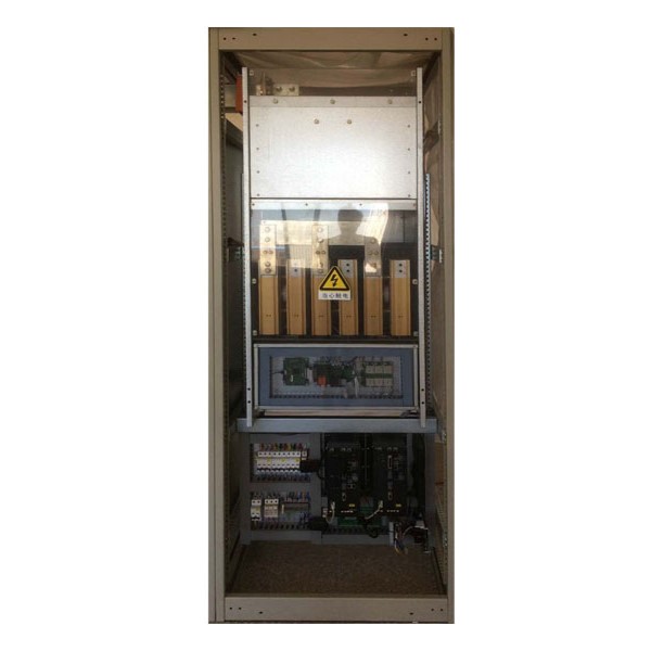
SLM Regenerative Rectifier – Energy Feedback Electrical Control Device
Brand name: HANI
Packing Details : Wooden box with fumigation or Wooden Fram or Steel Frame
Delivery Details: 30~60days or Based on the quantity
Shipping: Sea freight、Land freight、Air freight
HANI specializes in industrial electrical automation, delivering integrated drive and control solutions to safeguard your production.
Product Details
SLM Regenerative Rectifier – Energy Feedback Electrical Control Device
A comprehensive technical introduction to the SLM Regenerative Rectifier — an advanced industrial automation product that captures braking energy, feeds it back to the mains, and dramatically reduces operating costs across AC Drives & VFDs applications worldwide.
Key Function
100% Continuous Regenerative Feedback
Power Range
5 kW – 55 kW (Book-Size), up to 120 kW & beyond
Topology
IGBT-Based Non-Regulated Feed/Feedback
ROI Expectation
Typically Under 12–24 Months
1. What Is a Regenerative Rectifier — and Why It Matters
A Regenerative Rectifier is a power electronic device that converts three-phase alternating current (AC) into direct current (DC) to supply a common DC bus — and, crucially, also converts DC back into AC to return surplus energy to the mains grid. In conventional drive systems, braking energy generated when a motor decelerates or when a load overhauls is dissipated as heat through braking resistors. This is wasteful, adds thermal load to control cabinets, and requires additional cooling infrastructure. A Regenerative Rectifier eliminates that waste entirely: it captures the kinetic or potential energy of the motor and load, converts it into clean sinusoidal AC, and feeds it back to the power supply — delivering real, measurable Energy Feedback savings[reference:0].
The Smart Line Module (SLM) category of regenerative rectifier is often described as a “non-regulated” feed/feedback unit. Unlike fully regulated Active Line Modules (ALM), the SLM does not actively stabilize the DC bus voltage; instead, the DC link voltage follows the rectified AC input at approximately 1.35× the line voltage. This simpler control architecture nevertheless delivers 100% continuous regenerative feedback capability, making SLM-based Regenerative Rectifiers an extremely cost-effective entry point into energy recovery for AC Drives & VFDs systems[reference:2].
For engineers and procurement professionals sourcing industrial automation products, the appeal is straightforward: rather than purchasing, installing, and cooling a braking resistor network that simply burns money as heat, a regenerative rectifier turns braking events into recovered kilowatt-hours. As HANI’s technical team often emphasizes during site assessments, this is not a marginal efficiency tweak — it is a fundamental shift in how a production line manages its energy balance.
2. How the SLM Regenerative Rectifier Works: IGBT Topology & Energy Flow
2.1 From Diode Bridge to Active IGBT Rectification
A traditional 6-pulse diode rectifier converts AC to DC but allows current to flow in only one direction. When the motor regenerates, the DC bus voltage rises until a braking chopper activates and dumps energy into a resistor. This approach works but it wastes all the regenerated energy as heat[reference:3].
The SLM Regenerative Rectifier replaces the passive diode bridge with Insulated-Gate Bipolar Transistors (IGBTs), each paired with an anti-parallel freewheeling diode. This IGBT bridge enables bidirectional power flow: during motoring, the IGBTs (via their body diodes or synchronous rectification) supply DC power to the common bus; during regeneration, the IGBTs actively commutate in inverter mode, returning energy to the grid at the natural commutation point. The SLM is therefore classified as a “non-regulated” regenerative rectifier because it does not perform closed-loop DC bus voltage control — unlike an Active Front End (AFE), which uses PWM modulation to maintain a precisely regulated DC voltage with unity power factor[reference:4].
The IGBT-based topology used in SLM Regenerative Rectifiers inherently avoids the commutation failure risks associated with thyristor-based regenerative units. Thyristor (SCR) regenerative bridges can suffer “inverter tip” failures when grid disturbances cause commutation collapse; the IGBT, being a fully controllable switch, eliminates this vulnerability entirely[reference:6].
2.2 The Pre-Charge Circuit & DC Bus Management
Every SLM Regenerative Rectifier incorporates a critical pre-charge circuit. When the main contactor closes, the inrush current into the large DC-link capacitors would be enormous — equivalent to a momentary short circuit — without pre-charge protection. The pre-charge circuit routes current through a current-limiting resistor before bypassing it with a contactor once the capacitors reach approximately 85–90% of nominal DC bus voltage. This sequence typically completes within 1–2 seconds for chassis-type SLM modules[reference:8].
It is important to note that the pre-charge resistor dissipates energy as heat during each charge cycle; therefore, frequent power cycling (on-off-on within less than approximately 3 minutes) must be avoided to prevent thermal damage to the pre-charge resistors[reference:9]. This operational constraint is common to all SLM-based Regenerative Rectifiers and should be factored into system-level control logic.
2.3 The Common DC Bus Architecture
In multi-motor drive systems, the Regenerative Rectifier feeds a common DC bus from which multiple Motor Modules (inverters) draw power. When one motor is braking while another is motoring, energy is exchanged directly through the DC bus, bypassing the rectifier entirely. Only the net surplus energy is fed back to the grid. This common-DC-bus architecture using an SLM Regenerative Rectifier reduces the number of braking units, saves panel space, simplifies wiring, and improves overall system reliability[reference:10].
3. Technical Specifications — SLM Regenerative Rectifier Series
The following table presents the technical parameters of the standard SLM Regenerative Rectifier series, covering the Book-Size power range most commonly deployed in industrial automation products for machine tools, packaging lines, hoists, and general AC Drives & VFDs applications.[reference:11][reference:12]
| Parameter | SLM 5 kW | SLM 10 kW | SLM 16 kW | SLM 36 kW | SLM 55 kW |
|---|---|---|---|---|---|
| Input Voltage | 3-Phase 380–480 VAC ±10%, 47–63 Hz | ||||
| DC-Link Voltage (Nominal) | ~510–600 VDC (non-stabilized, ≈ 1.35 × Vline) | ||||
| Rated DC Output Current | ~9 A | ~18 A | ~27 A | ~60 A | ~90 A |
| Regenerative Feedback Capacity | 100% Continuous (deactivatable via parameter or digital input) | ||||
| Power Semiconductor | IGBT with anti-parallel diode (6-pulse bridge topology) | ||||
| DRIVE-CLiQ Interface | ✗ | ✗ | ✔ (1×) | ✔ (3×) | ✔ (3×) |
| Cooling Method | Internal forced-air cooling | ||||
| Form Factor | Book-Size (bookshelf) for cabinet mounting | ||||
| Pre-Charge Integration | Integrated pre-charge resistor & bypass contactor | ||||
| Protection Class | IP20 (standard cabinet installation) | ||||
| Grid Compatibility | Grounded TN/TT & ungrounded IT systems | ||||
Note: For larger power requirements (above 55 kW), chassis-type (cabinet-mounted) SLM regenerative rectifiers are available with power ratings up to approximately 120 kW and beyond. These units feature independent pre-charge contactor control, DRIVE-CLiQ communication, and support parallel connection for higher current capacity[reference:13].
4. Energy Feedback vs. Braking Resistors — The Real Economics
To understand why the SLM Regenerative Rectifier is increasingly selected for industrial automation products, one must compare the two braking philosophies side by side:
| Comparison Dimension | Braking Resistor Solution | SLM Regenerative Rectifier |
|---|---|---|
| Energy Disposition | Dissipated as heat — 100% wasted | Fed back to grid — typically >90% recovered |
| Thermal Load | Significant — requires cabinet ventilation/AC | Minimal — energy leaves the cabinet as electricity |
| Initial Hardware Cost | Low (resistor + chopper unit) | Moderate (IGBT module + line reactor) |
| Operating Cost | High — energy is purchased then burned | Low — energy is recycled, reducing utility bills |
| Continuous Braking Capability | Limited by resistor thermal rating | 100% continuous duty possible |
| Cabinet Footprint | Additional resistor cubicle often needed | Integrated — no external resistor required |
| Harmonic Performance | Standard 6-pulse diode THDi ~30–45% | With line reactor: significantly reduced harmonics |
| Typical Payback Period | N/A (ongoing cost, no payback) | 6–24 months (application-dependent) |
Control Engineering documented a real-world case study where a Regenerative Rectifier achieved 54% power savings in a frequent-run/stop application, with annual cost reductions exceeding USD 1,000 per drive[reference:14]. In high-intensity applications such as crane hoists, elevators, and centrifuges — where the motor operates in regenerative mode for a significant fraction of each duty cycle — the Energy Feedback savings from an SLM Regenerative Rectifier can reach 30–50% of total drive energy consumption. Yaskawa reports that its regenerative units (in the same product class as the SLM Regenerative Rectifier) deliver ROI in less than one year in elevator and crane applications[reference:15][reference:16].
For HANI’s customers in heavy manufacturing and material handling, the braking-resistor-versus-regenerative-rectifier decision is increasingly tilted by rising industrial electricity prices and corporate sustainability mandates. A Regenerative Rectifier aligns both financial and environmental objectives simultaneously.
5. Why the SLM Regenerative Rectifier Stands Out Among Industrial Automation Products
Non-Stabilized DC Bus — Lower Complexity, High Reliability
The SLM Regenerative Rectifier does not attempt closed-loop DC voltage regulation. The DC link voltage tracks the rectified AC input at approximately 1.35× Vline. This eliminates the need for complex PWM modulation on the grid side, reducing control complexity, switching losses, and component count compared to a fully regulated Active Front End (AFE). For applications that do not require a tightly regulated DC bus — which includes the vast majority of general-purpose AC Drives & VFDs installations — this is the optimal balance of functionality and cost[reference:17].
100% Continuous Feedback — No Duty-Cycle Derating
Unlike some add-on regenerative units rated for only 25% duty cycle (e.g., 60 seconds maximum on-time), the SLM Regenerative Rectifier is rated for 100% continuous regenerative feedback power. This makes it suitable for applications requiring sustained braking, such as downhill conveyors, unwinders, dynamometer test rigs, and crane lowering operations[reference:18][reference:19].
Built-In Pre-Charge & Protection
Every SLM Regenerative Rectifier integrates the pre-charge circuit, bypass contactor, overvoltage/undervoltage protection, and IGBT over-temperature monitoring. This reduces the number of external components, simplifies panel design, and shortens commissioning time. For system integrators building custom industrial automation products, this integration translates directly into lower engineering overhead and faster time-to-deployment.
IGBT Reliability — No Thyristor Commutation Failures
Thyristor-based regenerative rectifiers are vulnerable to commutation failure — a condition in which an incoming thyristor fails to turn on, causing a short circuit across the DC bus. The IGBT-based SLM Regenerative Rectifier eliminates this failure mode entirely, as IGBTs are fully controllable switches that do not depend on line commutation[reference:21]. This is a critical safety and reliability advantage in mission-critical industrial automation products.
6. Industrial Applications Where Regenerative Rectifiers Deliver Maximum Value
The SLM Regenerative Rectifier is particularly well suited to applications where the motor regularly operates in the 2nd and 4th quadrants (regenerative braking and overhauling loads). The following table summarizes key application sectors:
| Application Sector | Typical Equipment | Regenerative Duty Profile | Energy Saving Potential |
|---|---|---|---|
| Cranes & Hoists | Bridge cranes, gantry cranes, port container cranes, construction hoists | Lowering loads — continuous overhauling torque | 30–54% total energy savings |
| Elevators & Vertical Transport | Passenger elevators, freight elevators, escalators | Frequent start-stop; counterweight regeneration | 20–40% per elevator bank |
| Centrifuges & Separators | Decanter centrifuges, sugar centrifuges, industrial separators | High-inertia deceleration cycles; frequent braking | Significant — high-inertia kinetic energy recovery |
| Mining & Material Handling | Mine hoists, belt conveyors (decline), stacker/reclaimers | Overhauling loads on decline conveyors; cyclic hoisting | High — continuous regeneration possible |
| Test Stands & Dynamometers | Engine test rigs, motor dynamometers, transmission test benches | Absorbed power returned to grid instead of dissipated | Very high — near-continuous regeneration |
| Machine Tools | Spindle drives, high-speed cutting machines, grinding machines | Frequent acceleration/deceleration of high-inertia spindles | Moderate to high — cumulative savings across multi-spindle lines |
| Winders & Unwinders | Paper machines, foil rolling mills, textile winders, wire drawing | Continuous tension control with regenerative sections | 15–30% — tension regulation energy recovery |
7. Harmonic Performance & IEEE 519 Compliance
One of the secondary but important benefits of the IGBT-based Regenerative Rectifier is improved harmonic performance compared to a basic diode bridge. While the SLM itself is not an Active Front End and does not actively shape the input current waveform, it generates significantly cleaner regenerative current than a thyristor-based regenerative unit. When paired with the required input line reactor, the system achieves substantially lower Total Harmonic Distortion (THD) than a standard 6-pulse diode rectifier[reference:22].
For installations requiring strict compliance with IEEE 519-2014 (which limits current THD to <5% at the point of common coupling), an Active Front End (AFE) or Active Line Module (ALM) may be required instead of an SLM. However, for the majority of industrial environments where the Regenerative Rectifier is installed behind a dedicated transformer or where harmonic limits are less stringent, the SLM provides an excellent price-performance balance. The key distinction is as follows:
| Feature | SLM Regenerative Rectifier | ALM / AFE Regenerative Rectifier |
|---|---|---|
| DC Bus Voltage Control | Non-stabilized | Stabilized (e.g., 600 VDC constant) |
| Input Current Waveform | Improved (with line reactor) | Sinusoidal (PWM-shaped) |
| Power Factor | ~0.85–0.95 (with reactor) | ≈ 1.0 (adjustable) |
| IEEE 519 Compliance | Typically meets limits with reactor; verify per installation | Designed to comply (<5% THDi typical) |
| Cost | €€ (moderate) | €€€ (higher) |
For system integrators developing industrial automation products in markets where IEEE 519 compliance is mandatory, it is worth noting that certain manufacturers — including ABB with their ACS880 series and Fuji Electric with their RHC series — offer regenerative converters that combine the Energy Feedback capability of the Regenerative Rectifier with harmonic filtering to achieve THDi below 3–5%[reference:23][reference:24]. The SLM Regenerative Rectifier occupies the sweet spot between these premium-priced AFE solutions and the wasteful braking-resistor approach.
8. Installation, Commissioning & Best Practices
8.1 Mandatory Line Reactor
The SLM Regenerative Rectifier requires a matching input line reactor (choke) for proper operation. The reactor serves multiple functions: it limits current rate-of-rise during commutation, provides impedance for harmonic filtering, and protects the IGBT modules from grid-side voltage transients. Operating an SLM Regenerative Rectifier without the specified line reactor will result in excessive harmonic currents, increased IGBT stress, and potential premature failure[reference:25].
8.2 Pre-Charge Sequencing
The pre-charge sequence must be allowed to complete fully before the drive system is enabled. For chassis-type SLM Regenerative Rectifiers, the pre-charge process involves: (1) main contactor closure → (2) pre-charge contactor energization → (3) DC bus capacitor charging through the pre-charge resistor → (4) pre-charge completion signal (r899.11) → (5) bypass contactor closure → (6) operational ready state. The entire sequence typically requires 1–2 seconds. Failure to achieve pre-charge completion — indicated by fault F06000 (“Infeed: Precharging monitoring time expired”) — is most commonly caused by insufficient input voltage, DC bus short circuits, or pre-charge resistor damage from excessively frequent cycling[reference:26].
8.3 Regenerative Feedback Deactivation
The SLM Regenerative Rectifier supports disabling the regenerative feedback function via a digital input (for 5 kW and 10 kW modules) or via parameter setting (for 16 kW, 36 kW, and 55 kW modules). This capability is useful during commissioning, fault diagnosis, or when the connected grid cannot accept regenerated power (e.g., during generator-only operation on an islanded microgrid)[reference:28].
8.4 Cooling and Thermal Management
Although the SLM Regenerative Rectifier does not generate the extreme heat associated with braking resistors, it still requires adequate cooling. The internal fans provide forced-air cooling; the cabinet must be designed with sufficient airflow clearance (typically ≥ 100 mm above and below the module) and ambient temperature must not exceed the rated maximum (typically 40°C without derating). For chassis-type units operating in high-ambient environments, consider derating the continuous power rating or providing supplementary cabinet cooling.
9. Market Context: Industrial Automation & the Drive Toward Energy Efficiency
The global industrial automation market was valued at approximately USD 272.5 billion in 2025 and is projected to reach USD 299.2 billion in 2026, growing at a CAGR of 9.8%[reference:29]. Within this expanding market, energy-efficient drive technologies — including the Regenerative Rectifier — are among the fastest-growing segments, driven by rising industrial electricity tariffs, tightening carbon regulations, and corporate ESG commitments.
China’s 2025 Zero-Carbon Industrial Park policy (发改环资〔2025〕910号) explicitly calls for enterprises to benchmark against industry best practices, eliminate inefficient equipment, and implement energy-saving retrofits[reference:30]. In parallel, the EU Ecodesign Regulation (EU/2019/1781) exempts regenerative drives from certain efficiency requirements precisely because their net system efficiency far exceeds that of conventional drives — the regeneration capability itself constitutes the energy-saving measure[reference:31].
These regulatory tailwinds make the SLM Regenerative Rectifier a strategically timely choice for manufacturers upgrading their industrial automation products portfolio. The device not only delivers immediate operational savings but also positions facilities for compliance with evolving energy-efficiency mandates.
10. Competitive Landscape — How SLM Compares
Several major manufacturers offer Regenerative Rectifier products. The table below provides a comparative overview of key offerings in this industrial automation products segment:
| Manufacturer / Series | Type | Power Range | Feedback Efficiency | Harmonic Control |
|---|---|---|---|---|
| SLM Regenerative Rectifier (Non-Regulated) | IGBT, Non-Regulated | 5–120 kW+ | ~95% (continuous) | Line reactor required |
| ABB ACS880-14 Regenerative Drive Module | AFE, Regulated | 110–400 kW | >95% | THDi <3% (integrated filter) |
| Delta REG2000 / AFE2000 Series | Regenerative Unit | 7.5–55 kW | >95% | Built-in reactor; PF up to 0.99 (AFE2000) |
| Yaskawa R1000 Regenerative Unit | Add-On Regenerative Unit | 3.5–300 kW | High (DC bus interface) | PF ~0.9 at full load |
| Fuji Electric RHC Series | Regenerative Converter | 7.5 kW–4.8 MW | High | THDi reduced; PF=1 operation |
Among these options, the SLM Regenerative Rectifier distinguishes itself through its inherent simplicity: no complex PWM grid-side control, no stringent harmonic filtering requirements for most applications, and 100% continuous feedback capability — all at a moderate price point. For system integrators building cost-sensitive industrial automation products, this combination is difficult to beat.
11. Maintenance, Troubleshooting & Operational Guidance
11.1 Routine Maintenance
- Cooling fan inspection: Check fan operation every 6 months. Dust accumulation on fan blades and heatsinks reduces cooling efficiency and can lead to IGBT over-temperature trips. Clean using dry compressed air (low pressure).
- DC bus capacitor health: Electrolytic capacitors have a finite service life (typically 7–10 years under rated conditions). Periodically monitor DC bus ripple voltage; increasing ripple amplitude is an early indicator of capacitor degradation.
- Connection integrity: Inspect all power terminals, busbar connections, and PE (protective earth) connections annually. Thermal cycling can loosen bolted connections, increasing contact resistance and creating hot spots.
- Pre-charge circuit verification: Measure the pre-charge resistor value during annual maintenance. A significant deviation from the nominal value indicates thermal aging and may necessitate replacement[reference:32].
11.2 Common Faults and Solutions
| Fault Code / Symptom | Likely Cause | Recommended Action |
|---|---|---|
| F06000 — Precharging monitoring time expired | Insufficient input voltage, DC bus short/ground fault, or damaged pre-charge resistor[reference:33] | Verify 3-phase input voltage; check DC bus insulation resistance; measure pre-charge resistor; ensure ≥3 min between power cycles |
| DC Bus Undervoltage / Phase Loss | Missing input phase, low line voltage, or large voltage sag during motor starting | Check all three input phases; verify supply transformer capacity; inspect input fuses |
| IGBT Over-Temperature | Blocked airflow, fan failure, excessive ambient temperature, or sustained overload | Clean heatsinks; verify fan rotation; check ambient temp rating; reduce load or improve ventilation |
| Regenerative Feedback Not Activating | Feedback disabled via parameter or DI; grid unable to accept regenerated power | Check parameter p840 setting; verify DI status; confirm grid voltage within tolerance |
12. Frequently Asked Questions (FAQ)
Q1: What is the core function of an SLM Regenerative Rectifier?
The SLM Regenerative Rectifier converts 3-phase AC mains power into DC to supply a common DC bus for motor modules (inverters). Simultaneously, when connected motors operate in regenerative (braking) mode, the device converts the resulting DC energy back into AC and feeds it to the mains grid — enabling 100% continuous Energy Feedback. This eliminates the need for braking resistors and their associated heat dissipation in AC Drives & VFDs systems.
Q2: How does the SLM differ from an ALM (Active Line Module) or AFE (Active Front End)?
The SLM Regenerative Rectifier is non-regulated: the DC bus voltage is not actively controlled but follows the rectified AC input (≈1.35 × Vline). The ALM/AFE, by contrast, uses PWM modulation of IGBTs to regulate and stabilize the DC bus voltage at a setpoint (typically 600 VDC), delivers unity power factor, and produces sinusoidal input current with THDi <5%. SLM offers lower cost and complexity; ALM/AFE offers superior harmonic performance and voltage stability[reference:35].
Q3: Can the regenerative feedback function be disabled?
Yes. For 5 kW and 10 kW SLM Regenerative Rectifier modules, a digital input can disable the feedback function. For 16 kW, 36 kW, and 55 kW modules, the feedback can be enabled or disabled via parameterization. This is useful during commissioning, troubleshooting, or when the connected grid temporarily cannot accept regenerated power[reference:36].
Q4: Is a line reactor mandatory for the SLM Regenerative Rectifier?
Yes, absolutely. The matching line reactor (input choke) is mandatory for safe and reliable operation. It limits commutation current, provides harmonic filtering, and protects the IGBT power modules from grid-side voltage transients. Operating without the specified reactor risks IGBT damage and is outside the warranty conditions for all industrial automation products in this class[reference:37].
Q5: What is the typical ROI for installing a Regenerative Rectifier?
Payback periods depend heavily on the application duty cycle. For equipment with frequent regenerative braking (cranes, elevators, centrifuges, test stands), ROI is commonly achieved within 6–18 months. For intermittent regeneration applications, payback may extend to 2–3 years. Yaskawa reports ROI in less than one year for many crane and elevator installations using regenerative technology similar to the SLM Regenerative Rectifier[reference:38]. In all cases, the Regenerative Rectifier begins saving energy from its first day of operation.
Q6: Can multiple SLM Regenerative Rectifiers be connected in parallel?
Yes. SLM Regenerative Rectifiers — particularly chassis-type units — support parallel connection for higher total current capacity. For example, Siemens S120 SLM units can be configured in 12-pulse parallel arrangements (e.g., 4 SLMs in parallel) to increase total power and improve harmonic performance through phase-shifting transformer configurations[reference:39]. Consult the manufacturer’s engineering manual for derating factors and parallel connection requirements.
Q7: What grid types are compatible with the SLM Regenerative Rectifier?
The SLM Regenerative Rectifier is designed for connection to both grounded TN/TT systems and ungrounded IT systems. The input voltage range is typically 3-phase 380–480 VAC ±10% (with short-term dips down to -15% for <1 minute). The supply frequency range is 47–63 Hz[reference:40]. For IT (ungrounded) systems, specific grounding configurations apply — consult the installation manual for details.
13. A Word from HANI
At HANI, we believe that energy efficiency is not a luxury feature — it is a fundamental design principle that should be embedded in every industrial automation product we deliver. The SLM Regenerative Rectifier embodies this philosophy: it turns what was once waste heat into recoverable electrical energy, reducing both operating costs and carbon footprint in a single, elegantly engineered package.
Whether you are upgrading an existing AC Drives & VFDs installation or designing a new multi-motor production line, HANI’s application engineering team can help you select, size, and commission the right Regenerative Rectifier for your specific requirements. Contact us today for a preliminary energy-savings assessment.
SLM Regenerative Rectifier — Energy Feedback Electrical Control Device
Contact HANI for technical specifications, pricing, and application engineering support.
A smarter way to manage energy in industrial automation products and AC Drives & VFDs.
HANI is one of China’s leading professional industrial electrical automation manufacturers, providing complete drive and control solutions to customers worldwide. HANI focuses on designing and manufacturing integrated automation systems that meet the industry’s highest standards of precision, efficiency, and durability. Our engineering expertise lies in providing turnkey electrical automation projects to optimize the performance of modern industrial manufacturing plants.